LC-42AD5E/RU/S
5 – 4
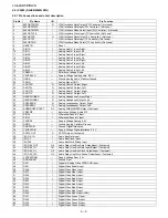
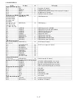
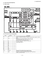
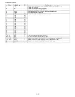
2.2. IC202 (RH-iXB964WJZZQ)
2.2.1 Pin Connections and short description
Pin No.
Pin Name
I/O
Pin Function
Clock and resets
32
NOT_RESET
I
Hardware reset, active low
15
XTAL_I
I
Analog Crystal oscillator input/external clock (2.5 V)
14
XTAL_O
O
Analog Crystal oscillator output
13
VDDA_2V5
—
Supply Analog oscillator supply (2.5 V)
16
VDDA_2V5
—
Supply Analog PLL supply (2.5 V)
Analog interface
1
RF_LEVEL
—
ADC 8 input for RF level monitoring
2
VDDA_2V5
—
Analog ADC 8 supply (2.5 V)
3
QP
—
Positive Q analog input for baseband configuration
4
QM
—
Negative Q analog input for baseband configuration
5
VDDA_ISO
—
Analog ISO nwell polarization (2.5 V)
6
VDDA_2V5
—
Analog ADC 12 supply (2.5 V)
7
REFP
—
Internal positive reference
8
REFM
—
Internal negative reference
9
INCM
—
Internal common mode
10
IM
—
Negative I analog input for IF and baseband configuration
11
IP
—
Positive I analog input for IF and baseband configuration
12
VDDA_1.0
—
Analog supply (1.0 V)
I2C interface
29
SDA
I/O
Serial data (open drain)
30
SCL
I
Serial clock (open drain)
21
SDAT
I/O
SDA tuner (open drain)
20
SCLT
I
SCL tuner
MPEG interface
43
D7
O
Serial MPEG data or parallel MPEG data (bit 7)
42
D6
O
Parallel MPEG data (bit 6)
40
D5
O
Parallel MPEG data (bit 5)
39
D4
O
Parallel MPEG data (bit 4)
37
D3
O
Parallel MPEG data (bit 3)
36
D2
O
Parallel MPEG data (bit 2)
35
D1
O
Parallel MPEG data (bit 1)
33
D0
O
Parallel MPEG data (bit 0)
44
CLK_OUT
O
MPEG byte or bit clock
46
STR_OUT
O
MPEG first byte sync
47
D/NOT_P
O
MPEG data valid/parity
48
ERROR
O
MPEG packet error
Front end controls
18
AGC_RF
I/O
RF AGC control
(5 V tolerant)
17
AGC_IF
I/O
IF AGC control
(5 V tolerant)
64
TEST
I/O
Reserved test mode, must be grounded.
27
GPIO0
I/O
General-purpose input/output port 0. Reserved test mode, must be grounded.
49
GPIO1
I/O
General-purpose input/output port 1
60
GPIO2
I/O
General-purpose input/output port 2 or lock indicator
59
GPIO3
I/O
General-purpose input/output port 3 or lock indicator
58
GPIO4
I/O
General-purpose input/output port 4
57
GPIO5
I/O
General-purpose input/output port 5
54
GPIO6
I/O
General-purpose input/output port 6
53
GPIO7
I/O
General-purpose input/output port 7
52
GPIO8
I/O
General-purpose input/output port 8. Reserved test mode, must be grounded.
61
GPIO9
I/O
General-purpose input/output port 9
23
AUX_CLK
I/O
Auxiliary clock
25
CS0
I
Chip select LSB
26
CS1
I
Chip select MSB
Power supply
19, 24, 31, 38,
45, 51, 55, 62
VDD_1V0
—
Digital core supply (1.0 V)
22, 28, 34, 41,
50, 56, 63
VDD_3V3
—
Digital I/O supply (3.3 V)
Summary of Contents for AQUOS LC-42AD5E
Page 4: ...LC 42AD5E RU S 1 1 LC 42AD5EB Service Manual CHAPTER 1 OPERATION MANUAL 1 SPECIFICATIONS ...
Page 5: ...LC 42AD5E RU S 1 2 2 OPERATION MANUAL ...
Page 6: ...LC 42AD5E RU S 1 3 ...
Page 7: ...LC 42AD5E RU S 1 4 ...
Page 8: ...LC 42AD5E RU S 1 5 ...
Page 9: ...LC 42AD5E RU S 1 6 ...
Page 10: ...LC 42AD5E RU S 1 7 3 DIMENSIONS Unit mm ...
Page 62: ...LC 42AD5E RU S 5 5 2 3 IC301 IC302 VHiTDA8931T 1Y 2 3 1 Block Diagram ...
Page 77: ...LC 42AD5E RU S 5 20 2 10 IC4203 RH iXC100WJZZQ 2 10 1 Block Diagram ...
Page 142: ...LC 42AD5E RU S 30 12 PACKING PARTS Not Replacement Item 㵘 S2 S4 S4 S4 S3 S7 S1 S4 S6 S6 S5 ...


