LC-42AD5E/RU/S
3 – 19
[7] Video signal adjustment procedure
* The adjustment process mode menu is listed in Section 5.
1. Signal check
1. Signal generator level adjustment check (Adjustment to the specified level)
2. Entering the adjustment process mode
1. Enter the adjustment process mode according to Section 3.
3. RF AGC adjustment
4. Tuner adjustment
• Composite signal PAL
: 0.7Vp-p
±
0.02Vp-p (Pedestal to white level)
Adjustment point
Adjustment Conditions
Adjustment procedure
1
Setting
[Signal]
PAL
Sprit Field Colour Bar
RF signal UV
[Terminal]
TUNER
• Feed the PAL Sprit Field colour bar signal to TUNER.
Signal level: 55 dB
µ
V + 1dB, -1dB (75
Ω
LOAD)
2
Auto adjustment
performance
Adjustment process
Page3
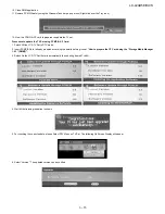
Bring the cursor on [
RF AGC ADJ] and press [OK]
[
RF AGC ADJ OK] appears when finished.
Adjustment point
Adjustment Conditions
Adjustment procedure
1
Setting
[Signal]
PAL
Full Field Colour Bar
RF signal
• Feed the RF signal (PAL colour bar) to TUNER.
• Make sure the PAL colour bar pattern has the sync level of 7:3 with
the picture level.
2
Auto adjustment
performance
Adjustment process
Page3
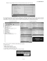
Bring the cursor on [
TUNER ADJ] and press [OK]
[
TUNER ADJ OK] appears when finished.
[E-12CH]
㸡
100% white
㸡
100% white
[RF Signal]
Summary of Contents for AQUOS LC-42AD5E
Page 4: ...LC 42AD5E RU S 1 1 LC 42AD5EB Service Manual CHAPTER 1 OPERATION MANUAL 1 SPECIFICATIONS ...
Page 5: ...LC 42AD5E RU S 1 2 2 OPERATION MANUAL ...
Page 6: ...LC 42AD5E RU S 1 3 ...
Page 7: ...LC 42AD5E RU S 1 4 ...
Page 8: ...LC 42AD5E RU S 1 5 ...
Page 9: ...LC 42AD5E RU S 1 6 ...
Page 10: ...LC 42AD5E RU S 1 7 3 DIMENSIONS Unit mm ...
Page 62: ...LC 42AD5E RU S 5 5 2 3 IC301 IC302 VHiTDA8931T 1Y 2 3 1 Block Diagram ...
Page 77: ...LC 42AD5E RU S 5 20 2 10 IC4203 RH iXC100WJZZQ 2 10 1 Block Diagram ...
Page 142: ...LC 42AD5E RU S 30 12 PACKING PARTS Not Replacement Item 㵘 S2 S4 S4 S4 S3 S7 S1 S4 S6 S6 S5 ...


