


76
Operating Instructions – MOVITRAC® B
5
Short description of important startup steps
Startup
be set to "off" if there is no braking resistor connected to MOVITRAC
®
B, which means
regenerative operation is not possible. In this operating mode, the MOVITRAC
®
B unit
attempts to extend the deceleration ramp. As a result, the generated power is not too
great and the DC link voltage remains below the switch-off threshold.
5.5.9
Setpoint specification (P10x)
P100 "Setpoint source" and P101 "Control source" can also be used for selecting a com-
munication interface as the setpoint or control signal source. However, the interfaces
are not automatically disabled with these parameters because the frequency inverter
must remain ready to receive data via all interfaces at any time.
Fixed setpoints always have priority over other setpoints. A complete list of selection op-
tions is included in the description of parameter P100.
Specification via
fieldbus/SBus
Select the value "SBus1 / fixed setpoint" for P100 to specify the setpoint via fieldbus or
SBus. The sign of the setpoint determines the direction of rotation.
Specification via
analog values
To specify the setpoint via analog values, you can select the following for P100:
• Bipolar (processing of signed value of analog input 1 or fixed setpoint)
• Unipolar (processing of absolute value of analog input 1 or fixed setpoint)
• Motor potentiometer (virtual potentiometer)
• Fixed se AI1 (sum of selected fixed setpoint and value of analog input AI1
→
P112 AI1 operating mode also applies)
• Fixed setpoint × AI1 (evaluation factor for analog input AI1
→
0 - 10 V = 0 - 100%)
• Bipolar AI2 (analog input 2 or fixed setpoint)
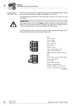
Specification via
fixed setpoint (digi-
tal control)
To select the digital inputs as setpoint source, set P100 to the value "frequency setpoint
input / fixed setpoint" (frequency at digital input DI04 specifies the setpoint). Use P102
"Frequency scaling" to determine at which input frequency the system setpoint 100 % is
reached.
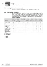
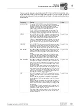
5.5.10 Protection functions
Parameterization
of current limit
(P303)
The internal current limitation refers to the apparent current, i.e. the output current of the
inverter. The inverter automatically decreases the current limit internally in the field
weakening range. In this way, the inverter implements a stall protection for the motor.
Parameterization
of speed monitor-
ing (P50x)
The drive reaches the speed specified by the setpoint only with adequate torque. When
the inverter reaches
P303 Current limit
it assumes that it will not reach the required
speed. Speed monitoring is triggered if the inverter exceeds the current limit for longer
than set in
P501 deceleration time
.
Parameterization
of fault responses
(P83x)
The fault "EXT. FAULT" triggers only in "ENABLED" inverter status.
P830
lets you set
the fault response that is triggered by an input terminal set to "/EXT. FAULT".
Parameterization
of motor protec-
tion (P340)
When this function is activated, MOVITRAC
®
B takes over the thermal protection of the
connected motor by electronic means. In most cases, the motor protection function is
comparable to standard thermal protection (motor protection switch) and, furthermore,
it takes account of speed-dependent cooling by the integrated fan. Motor utilization is
determined using the inverter output current, cooling type, motor speed and time. The
thermal motor model is based on the motor data entered during startup (MOVITOOLS
®
00
I
Summary of Contents for Movitrac B
Page 2: ...SEW EURODRIVE Driving the world...
Page 259: ......


