


100
Operating Instructions – MOVITRAC® B
5
Communication and unit profile
Startup
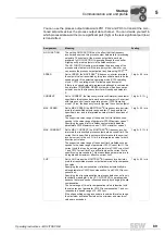
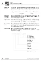
Status word defini-
tion
The status word is 16 bits wide. The less significant byte, the basic status block, consists
of 8 status bits with fixed definition that reflect the most important drive states. The as-
signment of the more significant status bits varies for different status words.
Basic status block
The basic status block of the status word contains the condition information required for
nearly any drive application.
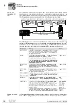
"Inverter ready"
signal
The value
inverter ready = 1
in status bit 1 of the status word indicates that the frequency
inverter is ready to respond to control commands from an external control. The inverter
is not ready, if
• MOVITRAC
®
B signals a fault
• The factory setting is active (setup)
• No supply voltage is present
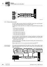
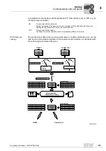
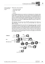
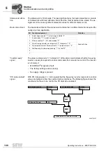
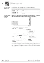
"PO data enabled"
signal
With
PO data enabled = 1
, bit 2 signals that the frequency inverter responds to control
values and setpoints from the communication interfaces. The following figure shows the
conditions that have to be met for the PO data to be enabled:
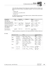
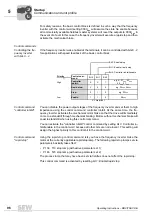
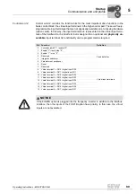
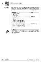
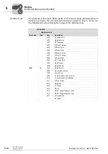
Bit Function/assignment
Definition
0
Output stage enabled "1" / output stage inhibited "0"
Fixed definition
1
Inverter ready "1" / inverter not ready "0"
2
PO data enabled "1" / PO data disabled "0"
3
Current ramp generator set: Integrator 2 "1" / integrator 1 "0"
4
Current parameter set: Parameter set 2 "1" / parameter set 1 "0"
5
Fault/warning: Fault/warning pending "1" / no fault "0"
6
7
5946738187
OR
AND
YES
876 Enable PO data
Status word bit 2: Enable PO data
100 Setpoint source
RS-485
SBus 1
101 Setpoint source
RS-485
SBus 1
00
I
Summary of Contents for Movitrac B
Page 2: ...SEW EURODRIVE Driving the world...
Page 259: ......


