


Operating Instructions – MOVITRAC® B
237
8
Technical data for braking resistors, chokes and filters
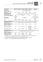
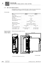
Technical data
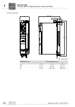
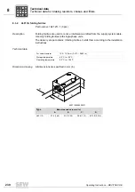
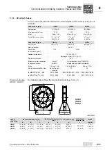
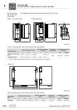
Dimension draw-
ings of HF...-403
output filters
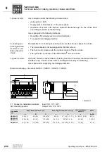
The following figure shows the mechanical dimensions in mm (in):
1472830731
Type
Main dimensions mm (in)
Mounting dimensions mm (in)
Hole
dimen-
sion mm
(in)
Ventilation clearances
mm (in)
Standard installa-
tion
Horizontal
mounting posi-
tion
A
B
C/C1
a
b
a1
a2
c
On the
side
Top
Bot-
tom
HF023-403
145
(5.71)
284
(11.2)
365/390
(14.4/15.4)
268
(10.6)
60 (2.4)
210
(8.27)
334
(13.1)
6.5 (0.26)
30 (1.2)
each
150
(5.91)
150
(5.91)
HF033-403
HF047-403
190
(7.48)
300
(11.8)
385/400
(15.2/15.7)
284
(11.2)
80 (3.1)
2705456011
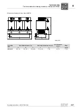
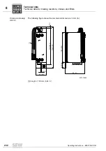
The ring cable lug must be attached directly to the copper clip.
Only the mounting position shown in the dimension drawing is permitted.
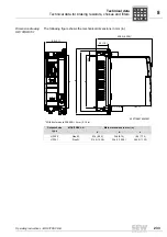
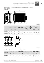
Output filter
type
Main dimensions mm (in)
Mounting dimen-
sions mm (in)
Hole dimension mm (in)
Ventilation clearances
mm (in)
A
B
C
a
b
c
d
On the
side
Top
Bot-
tom
HF180-403
480
(18.9)
260
(10.2)
510
(20.1)
430
(16.9)
180
(7.1)
18 x 13
(0.71 x 0.51)
11
(0.43)
192
each
(7.6)
510
(20.1)
510
(20.1)
b
c
a
4
5
6
7
U
V
W
b1
a1
c
A
C
U2
V2
W2
U1
V1
W1
d
c
A
C
B
a
b
P
i
f
kVA
Hz
n
Summary of Contents for Movitrac B
Page 2: ...SEW EURODRIVE Driving the world...
Page 259: ......


