


MOVIDRIVE
®
MD_60A, Absolute Positioning
23
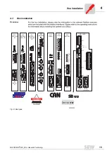
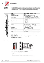
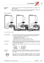
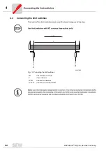
System bus
(SBus)
SBus wiring diagram
Cable specification
2
Ω
≤
Shield contact
Line length
→
→
→
→
Terminating
resistor
02205BEN
Fig. 14: System bus connection
X11:
X11:
X11:
REF1
AI11
AI12
AGND
REF2
REF1
AI11
AI12
AGND
REF2
REF1
AI11
AI12
AGND
REF2
1
2
3
4
5
1
2
3
4
5
1
2
3
4
5
X12:
X12:
X12:
DGND
SC11
SC12
DGND
SC11
SC12
DGND
SC11
SC12
1
2
3
1
2
3
1
2
3
S 12
S 11
S 12
S 11
S 11
S 12
ON OFF
ON OFF
ON OFF
y
y
y
Control unit
Control unit
Control unit
System bus
ref. potential
System bus
ref. potential
System bus
ref. potential
system bus high
system bus high
system bus high
system bus low
system bus low
system bus low
system bus
terminating resistor
system bus
terminating resistor
system bus
terminating resistor
Summary of Contents for movidrive md_60a
Page 1: ...MOVIDRIVE MD_60A Absolute Positioning Edition 03 2001 Manual 1051 0117 EN...
Page 2: ...SEW EURODRIVE...
Page 4: ...4 MOVIDRIVE MD_60A Absolute Positioning Documentation Safety and warning instructions...
Page 5: ...MOVIDRIVE MD_60A Absolute Positioning 5 2 1 Application fields 18...
Page 27: ...MOVIDRIVE MD_60A Absolute Positioning 27 Scaling 04442AEN Fig 18 Setting the scaling 0 0 I...
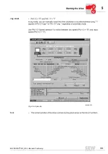
Page 33: ...MOVIDRIVE MD_60A Absolute Positioning 33 Jog mode Note 04448AEN Fig 24 Jog mode 0 0 I...
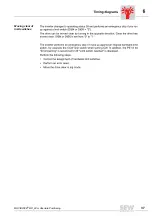
Page 37: ...MOVIDRIVE MD_60A Absolute Positioning 37 Moving clear of limit switches...
Page 39: ...MOVIDRIVE MD_60A Absolute Positioning 39 6 3 Error messages Display List of faults 01038AXX...
Page 42: ...10 2000...
Page 43: ...10 2000...