


Operating Instructions – MOVIAXIS® MX Multi-Axis Servo Inverter
79
4
Wiring diagrams
Installation
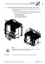
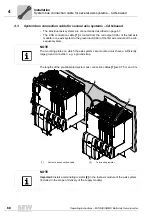
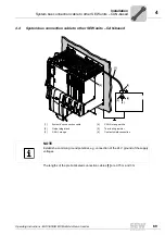
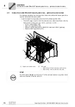
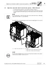
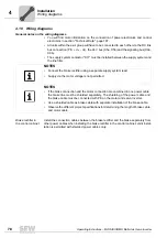
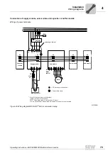
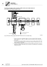
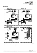
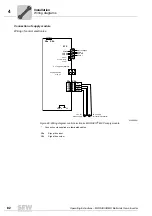
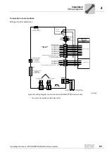
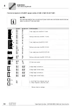
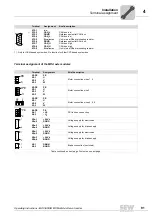
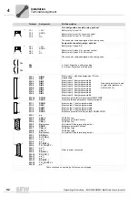
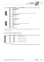
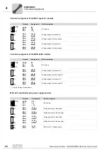
Connection of supply module, axis module and capacitor or buffer module
Wiring of power terminals
62359AEN
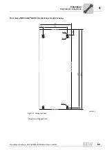
Figure 45: Wiring diagram MOVIAXIS
®
MX, recommended wiring
L1 L2 L3
L1´ L2´ L3´
Line filter
K11
L1
L2
L3
PE
X1
1
2
3
L1 L2 L3
PE
X4
-
+
PE
1
2
Supply module
X3
-R
+R
PE
1
2
Braking resistor
Affects
K11
When F16 (trip contact at overload relay)
triggers, K11 must be opened and
DI
∅∅
"Output stage enable" must receive a "0" signal.
F16 is a signal contact, which means the resistor circuit must not be interrupted.
X4
-
+
PE
Axis module
X2
X6
Motor
1
2
3
2
1
Brake
control
PE U V W
X4
-
+
PE
Axis module
-
+
PE
Axis module
F16 *
*
1
2
1
2
1
2
X4
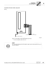
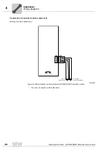
Cable length < 600 mm
X4
-
+
PE
Capacitor
module
1
2
PE
= PE (housing grounding point)
= Power shield clamp
Summary of Contents for MOVIAXIS MX
Page 2: ...SEW EURODRIVE Driving the world...
Page 210: ......
Page 211: ...SEW EURODRIVE Driving the world...


