


104
Operating Instructions – MOVIAXIS® MX Multi-Axis Servo Inverter
5
Supply module settings for a CAN-based system bus
Startup
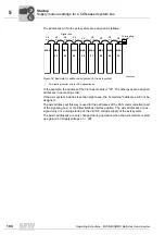
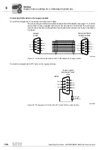
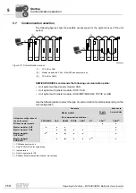
The addresses within the axis system are assigned as follows:
In the example, the address of the first axis module is "23". The other axes are assigned
addresses in ascending order.
If the axis system includes less than eight axes, the "remaining" addresses will not be
assigned.
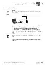
The axis address set this way is used for the addresses of the CAN communication (part
of the signaling bus) or the KNet fieldbus interface option. The axis addresses are as-
signed only once during startup of the 24V DC voltage supply of the axis system.
The basic addresses are only changed during operation when the axis module is start
up again (24 V supply voltage on / off).
62480aen
Figure 59: Example for address assignment in the axis system
*
Terminating resistor only for CAN transmission
X9
a / b
MXP
MXA
MXA
MXA
MXA
MXA
MXA
MXA
MXA
X9
a / b
X9
a / b
X9
a / b
X9
a / b
X9
a / b
X9
a / b
X9
a / b
X9
a / b
Signal bus
Terminating
resistor*
23
24
25
26
27
28
29
30
0
0
I
Summary of Contents for MOVIAXIS MX
Page 2: ...SEW EURODRIVE Driving the world...
Page 210: ......
Page 211: ...SEW EURODRIVE Driving the world...


