


46
Operating Instructions – MOVIAXIS® MX Multi-Axis Servo Inverter
3
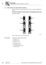
Multi-encoder card option XGH11A, XGS11A
Unit Design
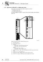
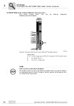
Restrictions for the evaluation of inputs for axis modules equipped with I / O and multi-encoder cards
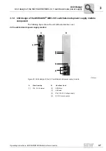
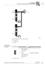
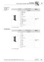
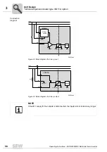
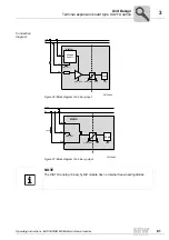
Wiring diagrams for encoders with external voltage supply
The wiring diagrams show the connection of one and two multi-encoder cards. For 12 V
encoders, external voltage supply only becomes necessary with two multi-encoder
cards if the total current of the encoders is
≥
800 mA.
Key see Figure 30.
NOTE
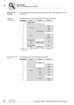
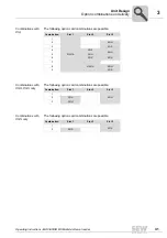
If the axis module is equipped with two I / O and one multi-encoder card or with one
I / O and two multi-encoder cards (see following table), the following restrictions apply
for the evaluation of inputs and outputs:
Evaluation is only possible for the inputs and outputs (if applicable) of two cards.
Variant
Plugged card
Plugged card
Plugged card
1
I / O card
I / O card
Multi-encoder card
2
I / O card
Multi-encoder card
Multi-encoder card
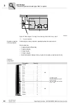
62357axx
Figure 29: Wiring diagram with one multi-encoder card
F
GND
+24 V
X61
X63 / X64
[1]
[2]
[3]
(DGND) 3
(+24 V) 4
Summary of Contents for MOVIAXIS MX
Page 2: ...SEW EURODRIVE Driving the world...
Page 210: ......
Page 211: ...SEW EURODRIVE Driving the world...


