5.1
Operating displays
The LED operating displays indicate the following:
H1 (red)
H2 (green)
Indication
OFF
OFF
Mains supply OFF
ON
OFF
Mains supply ON, inverter is ready for operation
OFF
ON
Inverter started
ON
ON
Inverter started and overload protection active
BLINKING
OFF
Fault indication by inverter (for fault information details
→
Sec. 5.3)
5.2
Operating conditions / Overload condition
Operating conditions:
Command
Operation
Drive response
STR or STL = “1“
Start
Inverter is ready for operation, drive is not running.
STR or STL = ”1”
and FSINA
≥
0.1 V
(or fixed frequency
selection)
Start +setpoint
Drive accelerates with ramp 32 RACC1 or 32 RACC2 in
selected direction of rotation.
Transition “0“ and ”1“ on
STR and STL
Reversal
Drive decelerates with ramp 33 RDEC1 or 35 RDEC2,
reverses and accelerates with ramp 32 RACC1 or 34 RACC2.
STR and STL = “1“
Important: not fail-safe!
Deceleration with
deceleration ramp
Drive decelerates with ramp 33 RDEC1 or 35 RDEC2.
STR and STL = “0“
Output voltage = 0
36 STOP = 0
→
motor uncontrolled, coasts to rest.
Stop with stop ramp
36 STOP > 0
→
motor decelerates with stop ramp 36 STOP.
Power down (K11)
EMERGENCY STOP
After power down wait for minimum 30s before you power
the inverter up again.
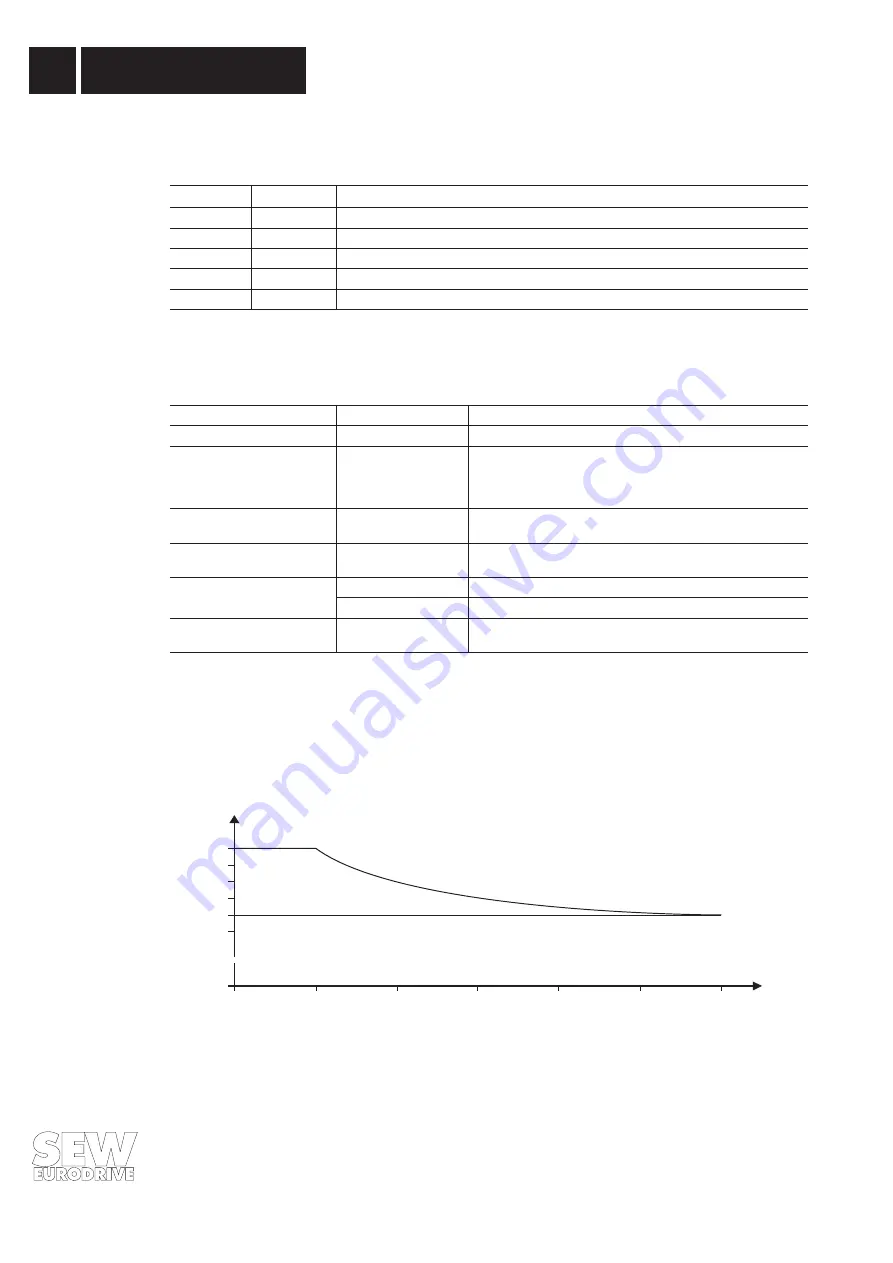
Overload condition:
An overcurrent of 150% I
N
for max. 60 seconds is permissible. If the thermal loading is too high the
Ixt monitoring will shut down the unit and generate a fault message (
→
Sec. 5.3).
Fig. 9: Overload characteristic
0041AEN
The overload rating is based on rated data, i.e. PWM frequency = 7.8 kHz (factory setting
→
4.4.2 PARA
74 PWM) and ambient temperature = 40 °C.
100
110
120
130
140
150
60
0
0
120
180
240
300
360
t/s
~
~
% I
Rated
5
Operation and Service
20
MOVITRAC
®
0500 - Operating Instructions


