background image

7

Operation

Manual mode with MOVISUITE®

Operating Instructions – MOVIMOT

®

 advanced

128

7.3.2

Control in manual mode

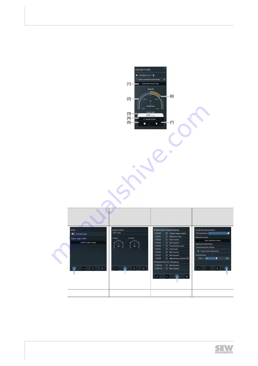
Manual mode window

Once manual mode has been successfully activated, you can control the device using
the controls in the MOVISUITE

®

 "Manual mode" window.

36028819001133963

Controller

1. Set the setpoint speed using the edit box [3] or graphic input [6].

2. To specify the direction of rotation, click the button [4].

3. To enable the device, click the button [7].

4. To stop the device, click the button [5].

The "Speed" group [2] shows the actual speed of the device.

Advanced functions and displays of manual mode

The following functions are available in manual mode using MOVISUITE

®

:

Release brake 

Disable output

stages

Actual values

Digital inputs and

outputs

Acceleration 

Reference travel

Timeout

[1]

[2]

[3]

[4]

Key [1]

Key [2]

Key [3]

Key [4]

25891936/EN – 05/2020

Summary of Contents for MOVIMOT advanced DRN DBC Series

Page 1: ...25891936_0520 Drive Technology Drive Automation System Integration Services Operating Instructions Mechatronic Drive Unit MOVIMOT advanced DRN DBC Binary Edition 05 2020 25891936 EN...

Page 2: ...SEW EURODRIVE Driving the world...

Page 3: ...3 2 Cable entry position 16 3 3 Nameplate positions 17 3 4 Example nameplate and type designation of the drive unit 18 3 5 Examples for the optional nameplate Electrical regulations UL CE in preparati...

Page 4: ...17 7 2 Binary controller 117 7 3 Manual mode with MOVISUITE 126 7 4 Function Releasing the brake deactivating DynaStop with FCB 01 129 7 5 Mechanical brake in connection with STO 131 8 Service 132 8 1...

Page 5: ...7 Line choke 252 11 8 Screw fittings 254 11 9 Connection cables 256 11 10 Mounting positions 258 11 11 Dimension drawings of the drive unit 259 11 12 Dimension drawings of plug connectors in the elect...

Page 6: ...licable documentation Refer to the corresponding documentation for all other components Always use the latest edition of the documentation and the software The SEW EURODRIVE website www sew eurodrive...

Page 7: ...ence s if disregarded Measure s to prevent the hazard Meaning of the hazard symbols The hazard symbols in the safety notes have the following meaning Hazard symbol Meaning General hazard Warning of da...

Page 8: ...l for fault free operation and fulfillment of any rights to claim under limited warranty Read the documentation before you start working with the product 1 6 Product names and trademarks The brands an...

Page 9: ...t As the user you must ensure that all of the work listed in the following is carried out only by qualified specialists Setup and installation Installation and connection Startup Maintenance and repai...

Page 10: ...th electrical installation startup troubleshooting and main tenance of the product who possess the following qualifications Qualifications in the field of electrical engineering in accordance with the...

Page 11: ...nection conditions are provided on the nameplate and in chapter Technical data in the documentation Always comply with the data and conditions Unintended or improper use of the product may result in s...

Page 12: ...motor Do not mount any additional loads The following figure depicts the position of the lifting eye of the motor without gear unit 9007224557044491 Remove the lifting eye before connecting the PE cab...

Page 13: ...an elevation of more than 3800 m above sea level The product can be used at altitudes above 1000 m above sea level up to 3800 m above sea level under the following conditions The reduction of the nom...

Page 14: ...present at all power connec tions as well as at any connected cables and terminals This also applies even when the product is inhibited and the motor is at standstill Do not separate the connection t...

Page 15: ...IMOT advanced drive unit MOVIMOT advanced drive unit The following figure shows an example of the MOVIMOT advanced drive units DRN80M4 BE DBC 1 2 4 DRN80MK4 DBC 1 2 3 9007228365550731 1 Electronics co...

Page 16: ...ped with the following cable entries Position X 2 3 X 2 x M25 x 1 5 2 x M16 x 1 5 1 x M16 x 1 5 only for option PE 2 2 x M25 x 1 5 2 x M16 x 1 5 1 x M16 x 1 5 only for option PE 3 2 M25 1 5 2 M16 1 5...

Page 17: ...0 0001 20 Inverter duty VPWM 3 IEC60034 Hz 50 kW 0 75 S1 Cos Th Kl i 19 58 kg 31 000 Nm 97 IM M1A 130 B 100 82 9 0 74 r min 1440 74 V230 400 A3 05 1 75 IE3 IP 54 CLP 220 Miner l 0 8 l 188 578 2 Jahr 2...

Page 18: ...rmany R87DRN100LS4 BE2HR DI DBC EI8Z IV 01 1234567890 0001 20 0055 IES2 3 IEC60034 ML P MA A nR Hz kW Nm 03 2 2 322 1 1400 fN 50 60 nA r min V 0 05 65 1 UN 380 500 IN 4 90 2603 382840 TEFC Made in Ger...

Page 19: ...or 5 Power factor of the motor power factor of the drive unit 0 99 6 Nominal torque of the motor 7 Nominal voltage of the motor depending on connection type 8 Nominal current of the motor depending on...

Page 20: ...on variant DFC Direct Fieldbus Communication DSI Direct System Bus Installation DAC Direct AS Interface Communication DBC Direct Binary Communication EI8Z Option EI8Z Single turn encoder with DDI conn...

Page 21: ...preparation 3 6 Examples for the optional nameplate Plug connector positions The nameplate is not attached to the device If the nameplate Plug connector posi tions has been ordered a nameplate is incl...

Page 22: ...18 18 32211237899 1 Cable glands 2 Connection box 3 Line connection L1 L2 L3 X1 only WITHOUT switch disconnector 4 Braking resistor connection 5 Plug connector connection unit for electronics cover 6...

Page 23: ...the electronics cover For the structure of the type designation refer to chapter Type designation of the electronics cover Eingang Input U AC 3x380 500V I AC 1 8A f 50 60Hz T 25 C 40 C ML 03 Status 00...

Page 24: ...55 5 5 A 5 Connection voltage 5 AC 500 V 0 Power section design EMC 0 Basic interference suppression 1 IT system design 3 Connection type 3 3 phase A Version 0 Device variant 0 Standard 0 Technology l...

Page 25: ...designation of connection unit The following table shows the type designation of the connection unit CU Product family CU Connection unit motor with electronics cover E Hardware design E For MOVIMOT...

Page 26: ...nameplate and type designation of connection unit Operating Instructions MOVIMOT advanced 26 C Version DI Option DI Digital interface MOVILINK DDI DE Digital interface MOVILINK DDI with encoder evalu...

Page 27: ...supply with suitable external measures be fore you start working on the device and secure it against unintentional reconnec tion to the voltage supply Secure the output shaft against rotation WARNING...

Page 28: ...ive unit s nameplate must match the voltage supply sys tem The drive unit is undamaged no damage caused by shipping or storage Ambient temperature according to the operating instructions nameplate and...

Page 29: ...does not influence cooling Balance components that were subsequently mounted to the shaft with a half key output shafts are balanced with a half key Use suitable cable glands for the supply leads use...

Page 30: ...ave to protect the cover and the wiring space from humidity dust or foreign particles Make sure that the cover is mounted properly Installing the electronics cover Use only electronics covers that mat...

Page 31: ...open Repair any damage to the paint work if necessary 4 4 4 Derating depending on the installation altitude Observe chapter Technical data and dimension sheets Technical data Derat ing factors 4 4 5...

Page 32: ...n included pressure compensation fitting option PE install the fit ting depending on the mounting position used The tightening torque is 4 0 Nm The following table shows the installation positions dep...

Page 33: ...ot surfaces Serious injuries Let the devices cool down before touching them 4 5 1 Blanking plugs Tighten the plastic blanking plugs included in the delivery by SEW EURODRIVE with 2 5 Nm Example The fo...

Page 34: ...mm 7 0 Nm EMC cable glands stainless steel 18216366 10 pieces M16 1 5 5 to 9 mm 4 0 Nm 18216382 10 pieces M25 1 5 11 to 16 mm 7 0 Nm Cable gland for exter nally routed Ethernet cable with mini IO plu...

Page 35: ...vanced 35 4 5 3 MOVIMOT advanced electronics cover Proceed as follows when installing the electronics cover Insert the screws and tighten them in diametrically opposite sequence step by step with a ti...

Page 36: ...residential areas This is a product with restricted availability in accordance with IEC 61800 3 This product may cause EMC interference In this case it is recommended for the user to take suitable me...

Page 37: ...s a conductive connection of drive unit and mounting plate In this case the entire contact surface must be conductive e g unpainted 2 PE conductor in the supply system cable 3 2 PE conductor via separ...

Page 38: ...884960907 Tightening torque of the cable gland Tightening torque of the M6 nut for stud bolt Part number M16 cable gland with M6 stud bolt 4 0 Nm 3 0 Nm 08189234 M25 cable gland with M6 stud bolt 7 0...

Page 39: ...not apply to IT system designs Voltage systems with grounded outer conductor Not permitted 5 3 2 Connecting supply system cables The nominal voltage and frequency of the device must correspond with t...

Page 40: ...ctor end sleeve With conductor end sleeve with or without plastic collar Connection cross sec tion 0 08 mm2 4 0 mm2 0 25 mm2 2 5 mm2 Stripping length 8 mm 9 mm Control terminals X9 Observe the permitt...

Page 41: ...line terminals X1a Line terminals X1a the following figure shows a schematic illustration 2 1 25649924107 5 3 6 Activating terminals X3 for the braking resistor Adhere to the following sequence when...

Page 42: ...residual current device RCD or a residual current monitoring device RCM is used for protec tion in the event of a direct or indirect contact only a type B RCD or RCM is per mitted on the supply end of...

Page 43: ...onductor end sleeve or using a straight rigid core is not permitted Recommendation Assembly with cable lug1 Permitted for all cross sections Assembly with solid connecting wire1 Permitted for cross se...

Page 44: ...connection is equipped with a plug connector for industrial applications according to IEC 60309 and if the supply system cable has a diameter of 2 5 mm2 INFORMATION The round M23 plug connectors of t...

Page 45: ...V phase to ground If safe electrical disconnection is required it must be implemented outside the unit for altitudes of 2000 m above sea level and higher safe electrical disconnection in accordance wi...

Page 46: ...VIMOT advanced MOVIMOT advanced MOVIMOT advanced Safety relay Supply system Control Back up fuse line protection Control cabinet level Field level Supply system Binary control signals 2 STO 1 DBC DBC...

Page 47: ...of the internal braking resistor Insulate and fasten the connections of the internal braking resistor Make sure all connections leading to other components are electrically insulated Connect the exter...

Page 48: ...onnection phase L1 OUT 12 L2 Black Line connection phase L2 OUT 13 L3 Gray Line connection phase L3 OUT X1a line terminals With option D11 switch disconnector 1 L1 Gray Line connection phase L1 IN 2 L...

Page 49: ...DC 24 V supply 14 DOR C Relay output DO R common contact 15 DI03 Digital input DI03 16 DI04 Digital input DI04 21 F_STO_P2 Yellow Input STO 22 F_STO_P2 Yellow Input STO to loop through 23 0V24_IN 0V24...

Page 50: ...ure shows the factory installed jumpers at the X9 terminals 1 2 3 4 11 12 13 14 21 22 23 24 5 6 15 16 25 26 X9 29006177419 These jumpers are not present in the following designs Designs with plug conn...

Page 51: ...face Control terminals 1 Analog input Line terminals Switch disconnector 2 3 32274774155 1 Jumpers installed at the factory for designs without plug connectors with STO function For additional informa...

Page 52: ...g accessory bag with installation materials for cable shielding exception Does not apply when all possible connections were ordered in plug connector design A1 Installation material for line and hybri...

Page 53: ...Instructions MOVIMOT advanced 53 5 7 2 General installation options The following figure shows the general installation options The following chapters show common examples and contain important notes...

Page 54: ...upply system connection Cable shielding Connect the shields of the cables to the metal housing of the unit using the shield clamps of the installation equipment kit To do so strip off the cable sheath...

Page 55: ...clamps for shielded cables e g control cables STO cables power cables you can use EMC cable glands which are available as an op tion to connect the shield 25216680843 5 8 2 Assembly of EMC cable gland...

Page 56: ...he designation of plug connectors is specified according to the following key X Terminal 2 Group 1 Power input 2 Power output 3 Encoder 4 Bus 5 Inputs and outputs 01 Function Function of the plug conn...

Page 57: ...s Cable routing Observe the permitted bending radii of the installed cables for cable routing For de tailed information refer to chapter Technical data Dimension sheets Plug con nectors including mati...

Page 58: ...when using third party cables This concerns in particular the following properties Mechanical properties e g IP degree of protection cable carrier suitability Chemical properties e g silicone and halo...

Page 59: ..._1 X5136 X1206 X2242 X1203_1 X1203_1 X5505 X5504 X5136 X1203_2 X5504 X5505 X4142 X4142 X5505 X5504 X1203_2 X1203_2 X5136 X1206 X2242 1 X1206 32288509835 Plug connectors Not together at a position with...

Page 60: ...onnection 3 X 2 or 3 X5505 Yellow STO 3 core connection 3 X 2 or 3 X4142 X5136 Digital inputs outputs X 2 or 3 X1203_2 X2242 X4142 Black Engineering interface X 2 or 3 X5505 X1524 1 Optional pressure...

Page 61: ...positions at the electronics cover The following figure shows the positions of the potentiometers and plug connectors f1 f2 f1 f2 X5231 9007228262316171 Designation Function f1 Potentiometer f1 under...

Page 62: ...e connection box M12 plug connectors at the connection box are pre installed so they match the con nection cables provided by SEW EURODRIVE Customers can adjust the orientation of plug connectors if r...

Page 63: ...lug connector using 3 Nm Between plug connector and bushing is a gap of 2 mm CAUTION Adjusting the right angle connector too often can damage it Potential damage to property Adjust the plug connector...

Page 64: ...vity Intercontec products with the matching coding for assembly by the customer Plug connector type Cable outer diame ter core cross section of crimp contacts Designation for order from the supplier T...

Page 65: ...ection The following table shows information about this connection Function AC 400 V connection for supplying the device for looping through Connection type M23 SEW insert 723 series SpeedTec capable...

Page 66: ...1 5 mm2 AC 500 V Open M23 coding ring black male Cable cross section 2 5 mm2 Connection cable Conformity part num ber Cable type Length in stallation type Cable cross sec tion operat ing voltage CE 18...

Page 67: ...m2 AC 500 V M23 coding ring black male M23 coding ring black male CE 18127479 HELUKABEL TOPFLEX 600 PVC Variable 2 5 mm2 AC 500 V Open M23 coding ring black male CE 18133967 HELUKABEL TOPFLEX 611 PUR...

Page 68: ...V M23 coding ring black male M23 coding ring black male CE 18133975 HELUKABEL TOPFLEX 611 PUR Halogen free Variable 4 mm2 AC 500 V M23 coding ring black male M23 coding ring black male UL 18153305 HE...

Page 69: ...CE 18133983 HELUKABEL TOPFLEX 611 PUR Halogen free Variable 4 mm2 AC 500 V Open M23 coding ring black male UL 18153321 HELUKABEL JZ 602 Variable 4 mm2 AC 500 V Open M23 coding ring black male UL 1815...

Page 70: ...18133983 18153321 18153348 Assembly Open cable end Description Prefabricated plug connectors D 3 2 1 PE C B A 5 4 6 Core color Core cross section Identi fication Assembly Signal Contact Black 1 5 mm2...

Page 71: ...connection Function AC 400 V connection IN Connection type MQ15 X Power male plug connector without union nut MURR Elektronik current load max 16 A Connection diagram PE B 1 2 3 A Assignment Contact...

Page 72: ...connection Function AC 400 V connection OUT Connection type MQ15 X Power female plug connector with union nut MURR Elektronik current load max 16 A Connection diagram PE A 3 2 1 B Assignment Contact S...

Page 73: ...4 V if the device does not have to fulfill any safety function The following table shows information about this connection Function Connection for safe torque off STO 3 cores Connection type M12 5 pin...

Page 74: ...r this connection Connection cables Conformity part num ber Cable type Length in stallation type Cable cross sec tion operat ing voltage CE UL 28110935 HELUKABEL LiYCY Variable 3 0 75 mm2 DC 60 V M12...

Page 75: ...L 28110994 igus chainflex CF78 UL Variable 4 0 5 mm2 DC 60 V M12 5 pin A coded female M12 5 pin A coded male CE UL 28111001 igus chainflex CF78 UL Variable 4 0 5 mm2 DC 60 V Open M12 5 pin A coded mal...

Page 76: ...ricated plug connectors 2 1 5 4 3 Core color Core cross sec tion Identi fication Assembly Signal Contact 1 Not pre fabricated DC 24 V auxiliary output 24V_OUT 1 White 0 75 mm2 Not pre fabricated F_STO...

Page 77: ...ctors 2 1 5 4 3 Core color Core cross sec tion Identi fication Assembly Signal Contact 1 Not pre fabricated DC 24 V auxiliary output 24V_OUT 1 Black 0 75 mm2 1 Not pre fabricated F_STO_P2 connection F...

Page 78: ...Only use the STO jumper plug when all incoming and outgoing STO connections have been removed from the device The following table shows information about this connection Function Connection for safe...

Page 79: ...this connection Connection cables Conformity part num ber Cable type Length in stallation type Cable cross sec tion operat ing voltage CE UL 28110935 HELUKABEL LiYCY Variable 3 0 75 mm2 DC 60 V M12 5...

Page 80: ...28110994 igus chainflex CF78 UL Variable 4 0 5 mm2 DC 60 V M12 5 pin A coded female M12 5 pin A coded male CE UL 28117816 igus chainflex CF78 UL Variable 4 0 5 mm2 DC 60 V M12 5 pin A coded female Ope...

Page 81: ...ricated plug connectors 1 4 3 2 5 Core color Core cross sec tion Identi fication Assembly Signal Contact 1 Not pre fabricated DC 24 V auxiliary output 24V_OUT 1 White 0 75 mm2 Not pre fabricated F_STO...

Page 82: ...ctors 1 4 3 2 5 Core color core cross sec tion Identi fication Assembly Signal Contact 1 Not pre fabricated DC 24 V auxiliary output 24V_OUT 1 Black 0 75 mm2 1 Not pre fabricated F_STO_P2 connection F...

Page 83: ...Disabling of the safety related disconnection of further devices due to parasitic voltages when using an STO jumper plug Severe or fatal injuries Only use the STO jumper plug when all incoming and ou...

Page 84: ...s P insert SpeedTec equipment 12 pin 0 coded coding ring without protected against con tact Connection diagram 9 1 2 7 6 5 11 12 3 4 8 10 Assignment Contact Signal Description 1 DI01 Digital input DI0...

Page 85: ...plug connectors that connect the shield with the device in an HF capable manner The following table provides an overview of the cables available for this connection Connection cable Conformity part nu...

Page 86: ...Not pre fabricated Digital input DI02 DI02 2 Red 0 25 mm2 Not pre fabricated Digital input DI03 DI03 3 Blue 0 25 mm2 Not pre fabricated Digital input DI04 DI04 4 Yellow 0 25 mm2 Not pre fabricated Re...

Page 87: ...ction Function Engineering interface CAN Connection type M12 SPEEDCON 5 pin female B coded color black Connection diagram 4 3 2 5 1 Assignment Contact Signal Description 1 Res Reserved 2 24V_OUT DC 24...

Page 88: ...of the cables available for this connection Connection cables Conformity part num ber Length in stallation type Operating voltage Connection to interface adapter USM21A CE 28139038 3 0 m DC 60 V M12...

Page 89: ...5 pin female A coded color black Connection diagram 1 4 3 2 5 Assignment Contact Signal Description 1 24V_OUT DC 24 V output 2 AIV1 Analog voltage input AI1 3 0V24 0V24 reference potential Reference p...

Page 90: ...ssible to work with a USB 3 0 interface You need the following components for the connection Component Part number USM21A interface adapter The following connection cables are included in the delivery...

Page 91: ...rface X31 at the connection unit in the connection box is assigned to the internal wiring of plug connector X4142 1 3 USB 2 X4142 32385960459 1 USB 2 0 connection cable commercial included in the USM2...

Page 92: ...5 minutes 3 Loosen the screws and remove the electronics cover from the connection box 4 Plug in the plug connector RJ10 from outside through one of the permitted cable entry bores for the permitted...

Page 93: ...options with a nominal voltage of 24 V to connector X31 such as Interface adapter USM21A CBG keypad Do not connect the following options with 5 V nominal voltage to the X31 con nector Interface adapt...

Page 94: ...or 9 pin male With RJ10 plug connector Length 3 m 28117832 USB connection cable USB A USB 2 0 Mini B For connecting the CBG keypad to the USB interface of the PC With USB A plug connector With USB 2 0...

Page 95: ...inal voltage of 24 V to connector X31 such as Interface adapter USM21A CBG keypad Do not connect the following options with 5 V nominal voltage to the X31 con nector Interface adapters USB11A UWS11A U...

Page 96: ...after disconnection from the power supply system Severe or fatal injuries Before removing the electronics cover de energize the device via a suitable ex ternal disconnection device Secure the device a...

Page 97: ...minimum switch off time of 10 s after switching off the voltage supply Do not switch the voltage supply on or off more often than once per minute INFORMATION Before startup remove the paint protection...

Page 98: ...using the parameter Releasing the brake deactivating DynaStop with FCB 01 enable 0 path Functions Drive functions FCB 01 Output stage inhibit Startup notes for lifting applications INFORMATION The rec...

Page 99: ...nger to persons or machines Required hardware components PC or laptop as specified in chapter PC connection Interface cable and if necessary interface adapter according to chapter PC con nection Requi...

Page 100: ...s are write protected Exception The parameter Startup mode in also be changed in Easy mode Expert mode Expert mode is a parameterization mode that allows full access to all device functions via the MO...

Page 101: ...1 2 3 4 S2 t1 On Off S1 1 2 3 4 3 4 3 4 1 2 3 1 2 3 4 S2 4 S2 t1 On Off f1 f2 4 3 2 1 ON 4 3 2 1 ON 3 5 6 4 7 ON 1 2 3 4 S1 ON 1 2 3 4 S2 ON 1 S3 6 4 7 4 3 2 1 O N O N 5 t1 2 3 4 5 6 7 8 9 10 6 5 f2 6...

Page 102: ...f1 The potentiometer f1 can be deactivated in Expert mode In this case the para meterizable replacement value is activated as speed setpoint f1 The following figure shows how to scale the speed setpoi...

Page 103: ...er f2 The potentiometer f2 can be deactivated in Expert mode In this case the para meterizable replacement value is activated as speed setpoint f2 The following figure shows how to scale the speed set...

Page 104: ...Acceleration 1 and Deceleration 1 of the fixed setpoint processing are activated 3 4 5 6 7 8 The following table lists the scaling of acceleration deceleration setpoint t1 depending on the setting of...

Page 105: ...ollowing figure shows the DIP switches of the drive unit S1 1 2 3 4 1 2 3 4 S2 4 S2 t1 On Off f1 f2 4 3 2 1 ON 4 3 2 1 ON 3 5 6 4 7 ON 1 2 3 4 S1 ON 1 2 3 4 S2 ON 1 S3 2 3 4 5 6 7 8 9 10 9007228267677...

Page 106: ...he functions of DIP switch S2 DIP switch S2 1 2 3 4 Meaning Reserved Source setpoint f1 Reserved Reserved ON Analog input AI1 OFF Potentiometer f1 You must not alter the factory setting of DIP switche...

Page 107: ...FCB 01 enable WARNING Risk from falling loads This can result in severe or fatal injuries Do not enable the function Releasing the brake deactivating DynaStop for hoist applications and applications w...

Page 108: ...limit for longer than 1 second factory settings the drive unit triggers the fault Speed monitoring The drive unit signals the fault for example via the DRIVE status LED The current limit must be reac...

Page 109: ...nction FCB 05 Speed control 6 6 2 Startup in Easy mode In Expert mode perform startup of the devices using the MOVISUITE engineering software of SEW EURODRIVE 25882306443 The startup procedure is divi...

Page 110: ...ault responses Overview Axis module Power supply monitoring Functions Setup Access rights Resetting device parameters Checklist for startup The following checklist lists the necessary steps for comple...

Page 111: ...2 Function keys Function according to bottom line on color display 3 RUN key Start 4 I key Information 5 STOP key Stop 6 OK key Acknowledgment 7 key Left 8 key Right 9 key Down 10 key Up 11 Function...

Page 112: ...uctions MOVIMOT advanced 112 Symbols used The available functions are shown with pictograms in the keypad display Startup Manual mode Optimization of the control mode Application Diagnostics Parameter...

Page 113: ...A keypad The following figure shows the CBG11A keypad 1 Color display OK STOP RUN Esc 1 4 3 7 6 5 9 8 2 2 Esc key 3 RUN key Start 4 STOP key Stop 5 OK key Acknowledgment 6 key Left 7 key Right 8 key D...

Page 114: ...configuration of the digital inputs is active Digital inputs Function Configuration of the digital inputs Setting CW CCW setpoint changeover DI01 Fixed setpoints positive rotation direc tion DI02 Fix...

Page 115: ...r Application limit positive speed or the parameter Application limit negative speed are used to scale the speed setpoint f1 For the application limit refer to the MOVISUITE parameter tree in the foll...

Page 116: ...ts the drive behavior after motor standstill Index Parameter Setting of parameter Behavior at standstill Behavior at motor standstill Brake Motoring position hold control Effect on the motor shaft 856...

Page 117: ...contacts Destruction of the switch contacts Do not operate the switch disconnector under load The switch disconnector of the device serves to interrupt the voltage supply of the electronics cover The...

Page 118: ...ion of rotation is pre scribed by the sign of the setpoint Fault reset Fixed setpoint processing mode Mechanical setting elements 3 Enable external fault setpoint changeover Positive direction of rota...

Page 119: ...es The fixed setpoint processing modes can be configured freely Fixed setpoint processing mode Functions of the setpoint sources Unipolar fixed setpoint Bipolar fixed setpoint Fixed setpoint analog se...

Page 120: ...setpoint t1 is active 1 0 1 0 x Illuminated in green The drive unit is running in positive direction of rotation clockwise rotation with speed setpoint f2 The acceleration setpoint t1 is active 1 1 0...

Page 121: ...n of the fixed setpoint The acceleration setpoint t1 is active 1 1 0 1 x Illuminated in green The drive unit is running with the fixed speed setpoint 3 The direction of rotation is specified by the si...

Page 122: ...th speed setpoint f1 2 The acceleration setpoint t1 is active 1 1 1 0 x Illuminated in green The drive unit is running in positive direction of rotation clockwise rotation with speed setpoint f2 The a...

Page 123: ...defined by the parameter Accel eration of the motor potentiometer function 1 1 0 x Illuminated in green The drive unit is running in positive direction of rotation clockwise rotation with decreasing...

Page 124: ...efined by the parameter Accel eration of the motor potentiometer function 1 1 0 x Illuminated in green The drive unit is running in negative direction of rotation counterclockwise rotation with the de...

Page 125: ...ction The acceleration setpoint t1 is active 1 1 0 0 120 kHz x Illuminated in green The drive unit is running in negative direction of rotation counterclockwise rotation with the speed setpoint define...

Page 126: ...nu item 27021619746386699 MOVITSUITE opens the Manual mode window 7 3 1 Activating deactivating manual mode Activation Manual mode can only be activated when the device is inhibited To activate manual...

Page 127: ...Manual mode with MOVISUITE Operating Instructions MOVIMOT advanced 127 Manual mode is deactivated When you click on the Deactivate manual mode button Or when you close the Manual mode window 25891936...

Page 128: ...sing the edit box 3 or graphic input 6 2 To specify the direction of rotation click the button 4 3 To enable the device click the button 7 4 To stop the device click the button 5 The Speed group 2 sho...

Page 129: ...top with FCB 01 enable 0 path Functions Drive functions FCB 01 Output stage inhibit In case the output stage is inhibited you can release the brake by a control signal di gital input or process data b...

Page 130: ...he brake deactivating DynaStop with FCB 01 2 to a digital input 2 18014420484362123 Control via process data bit not available with DBC designs Assign the function Releasing the brake deactivating Dyn...

Page 131: ...are revoked the drive deceler ates according to the active deceleration setpoint When the speed is 0 the brake remains released Motor position hold control is active Drive not energized brake applied...

Page 132: ...rating instructions 8 1 1 Motor malfunctions Fault Possible cause Measure Motor heats up ex cessively and trips with a fault Overload Measure power use larger motor or reduce load if necessary check t...

Page 133: ...W EURODRIVE Brake defective Contact SEW EURODRIVE Have brake replaced by SEW EURODRIVE Service or a qualified technician trained by SEW EURODRIVE Motor does not brake Brake lining worn Contact SEW EUR...

Page 134: ...In the parameter tree 6 select the Status node The current fault messages can be found in the Fault status 5 group Additional information on the causes for the Not ready status can be found in the Dev...

Page 135: ...cation limit For n 0 Brake applied and output stage off Application stop with output stage inhibit with self reset Emergency stop with output stage inhibit The inverter stops with the set emergency st...

Page 136: ...se failure val ues below threshold defined by the user index 8351 5 8622 4 No response Warning Application stop with out put stage inhibit Emergency stop with out put stage inhibit Inhibit output stag...

Page 137: ...ure current parame ter set prewarning 8442 5 No response Warning Application stop with out put stage inhibit Emergency stop with out put stage inhibit Inhibit output stage Electromechanical capa city...

Page 138: ...t Emergency stop with out put stage inhibit Inhibit output stage Application heartbeat timeout only with DSI designs Here you can set the device re sponse to a timeout of the applica tion heartbeat 86...

Page 139: ...t code Off Not ready for operation Line voltage absent Switch on the line voltage Yellow Flashes very rap idly 4 Hz Not ready for operation Initialization phase Wait for the initializa tion to be comp...

Page 140: ...e The drive is at the current limit Reduce the load Green Steady light Unit enabled The output stage is enabled The motor is in operation Yellow red Flashes with chan ging colors 1 Hz 2 yellow 2 red R...

Page 141: ...1 2 Brake fault 13 5 24 Encoder 1 fault 16 5 8 10 20 27 Startup fault 19 1 9 Process data fault 20 2 11 Device monitoring fault 23 4 Power section fault 25 2 7 20 21 30 31 61 70 Parameter memory monit...

Page 142: ...9 3 4 8 Control mode fault 10 2 99 Data Flexibility fault 11 7 8 Temperature monitoring fault 13 1 3 6 7 8 9 11 13 15 22 23 Encoder 1 fault 16 2 11 12 30 Startup fault 17 7 Internal processor fault 18...

Page 143: ...Connect a smaller motor Current supply Check the current supply Current transformer Check the current transformer Ramp limit deactivated and set ramp time too short Increase the ramp time Phase modul...

Page 144: ...stage of brake chopper defective Replace the defective brake chopper 8 7 4 Fault 6 Line fault Subfault 6 1 Description Line phase failure Response Line phase failure Cause Measure Missing line phase d...

Page 145: ...scription Speed monitoring generator mode Response Output stage inhibit Cause Measure Speed controller operates at setting limit mecha nical overload or phase failure in supply system or motor Increas...

Page 146: ...torque control with U f control mode Use a control mode that supports the required operating mode Connect an encoder if neces sary Select an operating mode that is supported by the current control mod...

Page 147: ...E Service Subfault 9 9 Description Parameter measurement not possible with active motor type Response Output stage inhibit Cause Measure Parameter measurement is possible only with asynchronous and sy...

Page 148: ...e Measure Memory area violated while accessing array For example an array access results in writing beyond the permitted memory range Check the program Subfault 10 4 Description Stack Response Applica...

Page 149: ...data see parameter list Subfault 10 9 Description CRC code Response Application stop output stage inhibit Cause Measure Wrong CRC checksum of code Load the program again The program memory is corrupt...

Page 150: ...ce the load Reduce the rms value of the output current Reduce the PWM frequency Ensure sufficient cooling Reduce the ambient temperature Subfault 11 3 Description Device utilization Response Output st...

Page 151: ...temperature sensor of heat sink Contact the SEW EURODRIVE Service 8 7 10 Fault 12 Brake Subfault 12 1 Description Brake output Response Application stop output stage inhibit Cause Measure No brake con...

Page 152: ...t Cause Measure Brake control has been activated although the hardware is not equipped with the matching module Select another brake type or brake connection Subfault 12 5 Description Short circuit Re...

Page 153: ...is faulty Subfault 13 2 Description Unknown encoder type Response Encoder 1 latest critical fault Cause Measure Encoder type not known and not supported by in verter Check the encoder type Contact SEW...

Page 154: ...rces light beam inter rupted reflector data cables etc Clean the sensor Subfault 13 6 Description Signal level too low Response Encoder 1 latest critical fault Cause Measure Vector below permitted lim...

Page 155: ...ne encoder Switch the device off and on again Check the wiring Check interference sources e g from the area of EMC Check the encoder Replace if necessary Note In Emergency mode manual mode you can mov...

Page 156: ...ause Measure Encoder signaled emergency Check interference sources e g from the area of EMC Check the startup parameters Note In Emergency mode manual mode you can move the drive using the motor encod...

Page 157: ...r is within the configured path range Check the limits Check for correct settings of encoder numer ator denominator factors Check interference sources e g from the area of EMC Check the startup parame...

Page 158: ...sing the motor encoder even if the external position encoder is faulty Subfault 13 19 Description Permanent low level in data line Response Encoder 1 latest fault Cause Measure Permanent low level of...

Page 159: ...lt critical Response Encoder 1 latest critical fault Cause Measure Encoder signaled internal fault Check the wiring Check interference sources light beam inter rupted reflector data cables etc Replace...

Page 160: ...Emergency mode manual mode you can move the drive using the motor encoder even if the external position encoder is faulty Subfault 13 26 Description Digital motor integration fault critical Response E...

Page 161: ...g up thermal model not yet completed Check the parameters of the thermal motor model and perform startup Subfault 16 5 Description Current limit smaller than magnetizing current of the motor Response...

Page 162: ...l position source in encoder as signment of the active drive train Index 8565 3 or 8566 3 If no encoder is installed activate the FCBs only using torque control or speed control op erating mode Subfau...

Page 163: ...ut stage inhibit Cause Measure During startup using nameplate data It is not possible to calculate the number of pole pairs ac curately from nominal frequency and nominal speed Enter the number of pol...

Page 164: ...rque Subfault 16 27 Description Maximum current or maximum torque not plausible Response Output stage inhibit Cause Measure During startup using nameplate data Maximum current or maximum torque not en...

Page 165: ...lt Subfault 17 7 Description Exception error Response Output stage inhibit Cause Measure Exception trap in CPU Contact the SEW EURODRIVE Service 8 7 14 Fault 18 Software error Subfault 18 1 Descriptio...

Page 166: ...ff and on again If the fault occurs repeatedly replace the device and send it together with the fault number to SEW EURODRIVE For further support contact SEW EURODRIVE Service Subfault 18 8 Descriptio...

Page 167: ...13 Description Calibration data Response Output stage inhibit System state Fault acknowledgment with CPU reset Cause Measure Calibration data not plausible Load valid calibration data 8 7 15 Fault 19...

Page 168: ...d via process data Specify an existing FCB number for FCB activa tion via process data Subfault 19 6 Description Mass moment of inertia setpoint violation Response Emergency stop output stage inhibit...

Page 169: ...eplace the device For further support contact SEW EURODRIVE Service Subfault 20 2 Description Supply voltage overload Response Output stage inhibit Cause Measure For MOVIDRIVE system the current load...

Page 170: ...tive Contact the SEWEURODRIVE Service Subfault 20 10 Description Fan supply voltage fault Response Emergency stop output stage inhibit Cause Measure Supply voltage of fan missing Check the connection...

Page 171: ...up or perform a new startup Subfault 21 4 Description Invalid label Response Output stage inhibit Cause Measure The connected drive contains invalid data Replace the drive Subfault 21 5 Description In...

Page 172: ...nent fault status Subfault 23 4 Description Hardware fault Response Output stage inhibit Cause Measure A fault occurred in a hardware component of the power section e g Overcurrent hardware com parato...

Page 173: ...VE Service Subfault 23 8 Description Parameter communication error Response Emergency stop output stage inhibit Cause Measure Power section communication interface detected error in parameter communic...

Page 174: ...Fault status parameter Manual fault reset The power section was replaced and differs in its power rating or voltage from the original power section Check whether the configuration is correct and repea...

Page 175: ...ronics version conflict Response Output stage inhibit Cause Measure Wrong version of calibration data of control elec tronics Contact the SEW EURODRIVE Service Subfault 25 16 Description Power section...

Page 176: ...lt 25 30 Description Initialization error replaceable memory module Response Output stage inhibit Cause Measure The formatting of the replaceable memory module does not match Restore delivery state NO...

Page 177: ...op output stage inhibit Cause Measure Failed to create restore point Delete restore point Subfault 25 70 Description Incompatible card configuration Response Emergency stop output stage inhibit Cause...

Page 178: ...URODRIVE Service Subfault 26 4 Description External braking resistor fault Response Response to external braking resistor fault Cause Measure External braking resistor s temperature switch connected t...

Page 179: ...dware limit switch and reference cam not flush Response Emergency stop output stage inhibit Cause Measure Hardware limit switch and reference cam not mounted flush Make sure that the reference cam and...

Page 180: ...se Measure The required test torque for the brake test is higher than the maximum torque It cannot be generated by the motor inverter combination Reduce the test torque Subfault 28 8 Description FCB 2...

Page 181: ...tor and motor cable for damage Subfault 28 12 Description FCB 25 Timeout during stator resistance measurement Response Output stage inhibit Cause Measure Motor parameter measurement activated while mo...

Page 182: ...limit switch current drive train Cause Measure Negative hardware limit switch approached Check hardware limit switch wiring Check target position Move clear of the hardware limit switch at posit ive...

Page 183: ...ear of software limit switch at positive speed Subfault 30 3 Description Limit switches swapped Response Emergency stop output stage inhibit Cause Measure Position value of negative software limit swi...

Page 184: ...verload Check whether the correct temperature sensor KY KTY was parameterized instead of PK Pt1000 Subfault 31 5 Description Temperature sensor prewarning motor 1 Response Thermal motor protection 1 p...

Page 185: ...sor Heat the motor Subfault 31 11 Description Temperature sensor wire break motor 2 Response Application stop output stage inhibit Cause Measure Connection to temperature sensor of motor 2 in terrupte...

Page 186: ...Temperature signaled by temperature sensor of motor 2 exceeds prewarning threshold Check for motor overload Subfault 31 16 Description Temperature model prewarning motor 2 Response No response Cause M...

Page 187: ...n signal period Check for correct setting of the EtherCAT SBusPLUS configuration in the MOVI C CONTROLLER Subfault 32 4 Description No synchronization signal Response External synchronization Cause Me...

Page 188: ...t local operation Scope measurement loaded from device Reset the fault Restart local operation Subfault 32 12 Description Manual mode timeout Response Manual mode timeout response Cause Measure Commun...

Page 189: ...e Measure Error checking compatibility of function block Contact the SEW EURODRIVE Service Subfault 33 8 Description SW function block configuration Response Output stage inhibit Cause Measure Error d...

Page 190: ...rary or Replaceable memory module Switch the device off and on again Subfault 33 13 Description Memory module removed Response Output stage inhibit System state Fault acknowledgment with CPU reset Cau...

Page 191: ...Measure Process data configuration changed during active process data operation Stop the process data and make your changes Then start the process data again Perform a reset Doing so will stop the pr...

Page 192: ...nology level Enter an activation key for the required technolo gy level You can find the required level in the pa rameter 8438 13 Technology level Required level Subfault 35 4 Description Activation k...

Page 193: ...nce Mechanical components cannot move freely or are blocked Make sure mechanical parts can move freely and check whether they are blocked Subfault 42 2 Description Jog mode lag error Response Output s...

Page 194: ...Set P component of the position controller to a larger value Speed controller parameters set incorrectly Check controller parameters Value of lag error tolerance too small Increase the lag error toler...

Page 195: ...DRIVE together with the fault number For further sup port contact SEW EURODRIVE Service Subfault 45 2 Description Option interface Response Fieldbus timeout response Cause Measure Basic device detects...

Page 196: ...ault 45 9 Description Fieldbus interface warning Response Warning Cause Measure Basic device detects non critical fault on internal interface for fieldbus connection Reset the fault If the fault occur...

Page 197: ...Subfault 46 2 Description Invalid variant Response Output stage inhibit Cause Measure Plugged safety card design does not match in verter type Remove the safety card Use the correct safety card desig...

Page 198: ...to the fault reported by the subcomponent index 8365 3 Subfault 46 52 Description Critical fault Response Output stage inhibit with self reset Cause Measure Safety card signals subcomponent fault of...

Page 199: ...rge Check the assignment of motor and inverter and check the dimensioning of the system Subfault 52 4 Description Parameterization of current limit characteristic Response Output stage inhibit Cause M...

Page 200: ...e the device via a suitable ex ternal disconnection device Secure the device against unintended re connection of the voltage supply Secure the output shaft against rotation Wait for at least the follo...

Page 201: ...minal output current the power at the output shaft will not be increased When you use an electronics cover with a lower nominal output current than the old electronics cover the power at the output sh...

Page 202: ...old memory module 5 Set the DIP switches on the new memory module in the same way as the control elements of the previous memory module 6 Insert the new memory module in the new electronics cover 7 Pl...

Page 203: ...ions replace a drive unit only with a drive unit with the same FS logo 5 Mount the drive unit Observe the Mechanical installation chapter 6 Remove the lifting eyes from the new drive unit Store the li...

Page 204: ...tions MOVIMOT advanced 204 8 8 4 Installing the lifting eye for motors without gear units 1 Remove the PE connection cable 2 Install the lifting eye for transportation as depicted in the following ima...

Page 205: ...shock caused by dangerous voltages in the connection box Dangerous voltages can still be present for up to 5 minutes after disconnection from the power supply system Severe or fatal injuries Before r...

Page 206: ...ion without further notice Instead of OS2 you can order OS3 For further information refer to chapter Surface protection 8 12 2 Storage conditions Observe the storage conditions specified in the follow...

Page 207: ...the drive according to the mounting position 8 12 3 Electronics INFORMATION For electronics components adhere to the following notes in addition to the notes in chapters Extended storage Drive and Ex...

Page 208: ...azardous to health and the environment These materials must be collected and disposed of separately Oil and grease Collect used oil and grease separately according to type Ensure that the used oil is...

Page 209: ...perating hours 3 group 27021619739284235 1 Display of operating and drive running hours performed 2 Display of active power and active energy 9 2 Inspection and maintenance intervals The following tab...

Page 210: ...ronics cover Replace the gasket if it is damaged or separating from the connection box Specialists at cus tomer site Varying depending on external factors Touch up or renew the surface anti corrosion...

Page 211: ...gainst rotation Before removing the electronics cover wait for at least the following time 5 minutes WARNING Risk of burns due to hot surfaces and hot gear unit oil Serious injuries Let the devices co...

Page 212: ...uring painting or re painting Potential damage to property Thoroughly cover the breather valves and sealing lip of the oil seals with strips prior to painting Clean the surface of the drive unit and m...

Page 213: ...mage to property When the cover is removed from the connection box you have to protect the cover and the wiring space from humidity dust or foreign particles Make sure that the cover is mounted proper...

Page 214: ...ible damage to prop erty Make sure not to damage the sealing surfaces when removing the gasket Loosen the used gasket by levering it off the retaining cams Doing so will be easier if you adhere to the...

Page 215: ...gloves for cleaning Work may only be carried out by qualified personnel Clean the sealing surfaces of the connection box and the electronics cover care fully 32170766603 6 Place the new gasket on the...

Page 216: ...of the drive unit using the applicable operating instructions 8 Place the electronics cover on the connection box again and fasten it Proceed as follows when installing the electronics cover Insert t...

Page 217: ...section Nm MG Required application torque with considera tion of the efficiency Nm Meff Effective thermally equivalent S1 torque Nm Mmax Maximum required application torque Nm Ma max Maximum output t...

Page 218: ...ent temperature C 10 2 1 Determining the motor data To select the proper drive you first need the data weight speed setting range etc of the machine to be driven This determines the torque and the rot...

Page 219: ...inverter This is a highly simpli fied illustration that serves to clarify the process For example the following points are left out Reduction of the available nominal torque at low speeds Capacity ut...

Page 220: ...x nmax Check individually for all n travel sections Take L into account in motor mode Take L into account in generator mode Gear unit selection Overhung load test necessary Overhung load Calculation f...

Page 221: ...ct planning With selected connection type Select drive according to table Check drive application Select encoder Setting range smaller 1 10 With delta connection type smaller 1 20 Mmax nmax nmin nmax...

Page 222: ...222 Check BW according to braking energy and brake applications per hour END with ne 140 145 min 1 nmin na with ne 1 min 1 nmin na With delta connection type Yes Yes Yes No Meff t1 M1 2 tn Mn 2 t1 tn...

Page 223: ...following specifications Load weight m 2 500 kg Conveying speed v 22 m min Positioning speed v 5 m min Acceleration a 0 4 m s2 Number of rollers a 8 Efficiency of the application with rollers app 0 7...

Page 224: ...the calculations for the application that are required to de termine the drive units Calculations Static resistance to vehicle motion F m g D x d f c mm x m R bearing 2 2 2 140 0 005 28 m m F kg F R...

Page 225: ...al bevel gear units of size K 37 meet this requirement 2 Selecting the gear ratio with suitable output speed Requirement The application calculations result in a maximum required output speed of nmax...

Page 226: ...5 5 A Nominal power PN 0 37 kW 0 55 kW 0 75 kW 1 1 kW 1 5 kW 2 2 kW Nominal torque MN 2 5 Nm 3 65 Nm 4 95 Nm 7 2 Nm 9 8 Nm 14 5 Nm Overload capacity of MN 200 200 200 200 200 200 4 Checking further to...

Page 227: ...Nm which corresponds to a torque requirement at the motor shaft of 45 1 Nm 24 99 Meff i 1 8 Nm The selected motor inverter combination DRN80MK4 D with the assigned inverter 2 0 A has a nominal torque...

Page 228: ...11 8 W Deceleration ramp 0 92 s 6 brake applications per hour Calculating the energy from the power of the deceleration ramp W P t W s J 11 8 0 92 10 9 The specified deceleration ramp in seconds refer...

Page 229: ...e gear units have higher tooth friction losses and lower efficiency than R F or K gear units Other factors influencing the efficiency Gear ratio of the helical worm or SPIROPLAN stage Input speed Ambi...

Page 230: ...ox 2 SPIROPLAN W10 to W30 SPIROPLAN W37 to W47 i range reduction i range reduction approx 35 75 approx 15 approx 20 35 approx 10 approx 10 20 approx 8 approx 30 70 approx 8 approx 8 approx 5 approx 10...

Page 231: ...the thermal rating based on the actual operating conditions The thermal rat ing of the gear unit can be increased by appropriate measure e g by using a synthetic lubricant with higher thermal enduranc...

Page 232: ...Provided that the installation notes are followed the re quirements for CE marking of the entire machine system equipped with these units on the basis of the EMC Directive 2014 30 EU are met For detai...

Page 233: ...well within the maximum permissible noise levels set forth in ISO 8579 1 for gear units and EN 60034 9 for motors 11 2 3 Paint Drive units are coated with blue gray RAL 7031 according to DIN 1843 mac...

Page 234: ...A 2 5 A 3 2 A 4 0 A 5 5 A Nominal line voltage AC to EN 50160 Uline 3 x 380 500 V Nominal line current AC Iline 1 05 A 1 33 A 1 80 A 2 63 A 3 51 A 4 90 A Line frequency fline 50 60 Hz 10 Input connec...

Page 235: ...n 1 1400 min 1 1400 min 1 1400 min 1 1400 min 1 1400 min 1 Nominal motor current IMot 1 02 A 1 29 A 1 75 A 2 55 A 3 4 A 4 75 A Motor efficiency 50 74 3 78 6 80 7 83 5 84 6 86 4 75 77 3 81 0 82 9 85 0...

Page 236: ...7 25 Nm Overload capacity of MN 200 200 200 200 200 Nominal speed nN 2900 min 1 2900 min 1 2900 min 1 2900 min 1 2900 min 1 Nominal motor current IMot 0 95 A 1 13 A 1 42 A 2 07 A 2 96 A Brake type1 B...

Page 237: ...gear unit ratio Set the torque limit of the inverter accordingly Refer to the MOVIMOT advanced Gear motos catalog for the maximum permitted output torques for MOVIMOT advanced with gear units PWM fre...

Page 238: ...ory II Proof of mechanical strength Class 3M5 5M1 according to DIN EN 60721 3 3 5 General information MOVIMOT advanced No of times power may be switched on off 1 per minute Minimum switch off time for...

Page 239: ...60 C deviating to the standard non condensing no moisture condensation IN motor reduction 3 IN per K at 40 C to 60 C Chemically active sub stances Long term storage weatherproof EN 60721 3 1 class 1C...

Page 240: ...erating factors Derating depending on the ambient temperature The following figure shows the IN reduction depending on the ambient temperature Ambient temperature in C Motor current rms value N 40 20...

Page 241: ...4000 m 3800 m 5000 m fAH 25852074635 Notes INFORMATION Derating is based on typical operating conditions with a supply voltage of 24 V sensor supply input voltage of STO input 11 3 4 Current carrying...

Page 242: ...l of all connected sensors actuators maximum individual load 100 mA Permitted total current for external supply 100 mA total of all connected sensors actuators maximum individual load 100 mA 11 3 7 Re...

Page 243: ...Maximum Input voltage range X9 1 and X9 21 DC 3 V DC 24 V DC 30 V Input capacitance against STO_M 300 pF 500 pF Input capacitance against GND 300 pF 500 pF Power consumption at DC 24 V F_STO_P1 150 mW...

Page 244: ...Single turn absolute encoder 12 bits 4096 inc MOVILINK DDI coaxial 11 3 11 Technical data of the CBG keypads Keypad CBG11A CBG21A Part number 28232646 28238133 Interfaces D sub 9 pin female CAN inter...

Page 245: ...ake chopper Small amount of regenera tive energy Integrated braking resistor Medium large amount of re generative energy External braking resistor 11 4 2 Integrated BW1 braking resistor The following...

Page 246: ...re braking energy The diagram permits 290 J of braking energy for the 0 2 s deceleration ramp and 200 cycles per hour In this case the required 288 J can be dissipated via BW1 11 4 3 External braking...

Page 247: ...285 75 174 mm 435 75 174 mm Prescribed connection cables Shielded cables with a temperature resistance of Tamb 90 C 194 F Maximum permitted cable length 15 m 15 m 11 4 4 Technical data of BW100 005 K...

Page 248: ...following figure shows the dimensions of the external braking resistor BW150 003 K 1 5 110 146 10 6 60 15 15 5 80 98 4 6 8 1500 25298773259 Dimension drawing of BW100 005 K 1 5 The following figure sh...

Page 249: ...s in mm Mounting dimensions mm Mass kg A B C b d e a x BS 005 60 160 252 125 4 20 6 17 5 0 5 11 4 5 Technical data of BW150 006 T and BW100 009 T Power diagrams The following figure shows the rating d...

Page 250: ...l braking resistor BW150 006 T 75 110 174 162 7 166 65 100 285 7x11 25298808587 Dimension drawing of BW100 009 T The following figure shows the dimensions of the external braking resistor BW100 009 T...

Page 251: ...environments prone to condensa tion and atmospheres with low humidity or contamination such as applications out doors under roof or with protection Similar to corrosivity category1 C2 low Systems in s...

Page 252: ...approval independent of the drive unit 11 7 2 Technical data Line choke ND0070 503 ND0160 503 ND0300 503 ND0420 503 Part number 17984173 17984181 17983800 17983819 Nominal line voltage UN 3 AC 230 V 5...

Page 253: ...imension drawing d b B E C a A 31249196171 Line choke Main dimensions in mm Mounting dimensions in mm Connection A B C E a b d PE ND0070 503 78 57 105 56 65 40 4 8 M4 ND0160 503 96 70 120 65 71 54 4 8...

Page 254: ...8 Nm 18247350 Pressure com pensation screw fittings made of stain less steel 1 piece M16 1 5 4 Nm 28214617 EMC compliant cable gland brass nickel plated 10 pieces M16 1 5 4 Nm 5 to 9 mm 18204783 10 pi...

Page 255: ...read made of stainless steel 10 pcs M12 1 0 2 3 Nm 18202799 M12 plug for plug con nector with female thread made of stain less steel 10 pcs M12 1 0 2 3 Nm 18202276 1 The specified torques must be adhe...

Page 256: ...mm2 Copper Insulation Polypropylene 0 24 mm Colors DIN 47100 yellow green pink gray blue red black purple pink and gray red and blue brown white 2 Inner sheath ing TPE O halogen free Color Nature 3 F...

Page 257: ...Hz 1 min Operating voltage Max AC 300 V UL Insulation resis tance 500 M km Operating tempera ture 50 C to 80 C fixed installation 30 C to 80 C cable carrier 20 C to 60 C cable carrier with mechanical...

Page 258: ...otors with IEC flange Position of electronics cover and cable entry The following figure shows the mounting positions of the MOVIMOT advanced drive unit with IEC flange T 270 L 180 B 90 R 0 X X X X 3...

Page 259: ...Scope of delivery Standard parts supplied by SEW EURODRIVE Standard parts not supplied by SEW EURODRIVE Tolerances Breather valves and cable glands The dimension drawings always show the screw plugs...

Page 260: ...mension drawings of the drive unit Operating Instructions MOVIMOT advanced 260 11 11 2 MOVIMOT advanced1 1 For gearmotor dimension sheets refer to the MOVIMOT advanced Gearmotors catalog 71M L 252 LB...

Page 261: ...11 Technical data and dimension sheets Dimension drawings of the drive unit Operating Instructions MOVIMOT advanced 261 71M L 252 LB B5 B14 222 LB B3 220 25891936 EN 05 2020...

Page 262: ...11 Technical data and dimension sheets Dimension drawings of the drive unit Operating Instructions MOVIMOT advanced 262 71M LS 319 LBS B5 B14 289 LBS B3 287 25891936 EN 05 2020...

Page 263: ...11 Technical data and dimension sheets Dimension drawings of the drive unit Operating Instructions MOVIMOT advanced 263 71M LS 319 LBS B5 B14 289 LBS B3 287 25891936 EN 05 2020...

Page 264: ...11 Technical data and dimension sheets Dimension drawings of the drive unit Operating Instructions MOVIMOT advanced 264 80MK 80M L 281 327 LB B5 B14 241 287 LB B3 239 285 25891936 EN 05 2020...

Page 265: ...11 Technical data and dimension sheets Dimension drawings of the drive unit Operating Instructions MOVIMOT advanced 265 80MK 80M L 281 327 LB B5 B14 241 287 LB B3 239 285 25891936 EN 05 2020...

Page 266: ...11 Technical data and dimension sheets Dimension drawings of the drive unit Operating Instructions MOVIMOT advanced 266 80MK 80M LS 362 408 LBS B5 B14 322 368 LBS B3 320 366 25891936 EN 05 2020...

Page 267: ...11 Technical data and dimension sheets Dimension drawings of the drive unit Operating Instructions MOVIMOT advanced 267 80MK 80M LS 362 408 LBS B5 B14 322 368 LBS B3 320 366 25891936 EN 05 2020...

Page 268: ...11 Technical data and dimension sheets Dimension drawings of the drive unit Operating Instructions MOVIMOT advanced 268 90S 90L L 331 363 LB B5 B14 281 313 LB B3 279 311 25891936 EN 05 2020...

Page 269: ...11 Technical data and dimension sheets Dimension drawings of the drive unit Operating Instructions MOVIMOT advanced 269 90S 90L L 331 363 LB B5 B14 281 313 LB B3 279 311 25891936 EN 05 2020...

Page 270: ...11 Technical data and dimension sheets Dimension drawings of the drive unit Operating Instructions MOVIMOT advanced 270 90S 90L LS 425 457 LBS B5 B14 375 407 LBS B3 373 405 25891936 EN 05 2020...

Page 271: ...11 Technical data and dimension sheets Dimension drawings of the drive unit Operating Instructions MOVIMOT advanced 271 90S 90L LS 425 457 LBS B5 B14 375 407 LBS B3 373 405 25891936 EN 05 2020...

Page 272: ...11 Technical data and dimension sheets Dimension drawings of the drive unit Operating Instructions MOVIMOT advanced 272 100LS 100LM L 369 419 LB B5 B14 309 359 LB B3 307 357 25891936 EN 05 2020...

Page 273: ...11 Technical data and dimension sheets Dimension drawings of the drive unit Operating Instructions MOVIMOT advanced 273 100LS 100LM L 369 419 LB B5 B14 309 359 LB B3 307 357 25891936 EN 05 2020...

Page 274: ...11 Technical data and dimension sheets Dimension drawings of the drive unit Operating Instructions MOVIMOT advanced 274 100LS 100LM LS 462 512 LBS B5 B14 402 452 LBS B3 400 450 25891936 EN 05 2020...

Page 275: ...11 Technical data and dimension sheets Dimension drawings of the drive unit Operating Instructions MOVIMOT advanced 275 100LS 100LM LS 462 512 LBS B5 B14 402 452 LBS B3 400 450 25891936 EN 05 2020...

Page 276: ...the electronics cover Operating Instructions MOVIMOT advanced 276 11 12 Dimension drawings of plug connectors in the electronics cover The following figure shows the additional dimensions of the plug...

Page 277: ...tion For more information refer to chapter Plug connector positions 7 6 2 4 1 5 30 32 56 2 1 69 2 501 562 18 16 3 22 6 50 1 56 2 6 501 562 32379545483 1 Straight plug connector variant 2 Right angle p...

Page 278: ...g radii of the optional plug connectors including mating connector in connection with prefabricated cables from SEW EURODRIVE For more information refer to chapter Plug connector positions R 2 8 4 28...

Page 279: ...n the following standards and safety classes Underlying standards Safety class underlying standard Performance Level PL according to EN ISO 13849 1 Safety Integrity Level SIL according to EN 61800 5 2...

Page 280: ...nects the safety related STO in put via a 2 pole 24 V switching signal sourcing sinking when a connected com mand device e g emergency stop button with latching function is activated This activates th...

Page 281: ...ns MOVIMOT advanced 281 12 2 4 Schematic representation of the safety concept Uz Uz 2 4 5 6 1 3 23543720971 1 STO function 2 Drive control 3 Internal safety card optional 4 Diagnostics and inhibiting...

Page 282: ...controller safety re lay The following figure shows the STO function v t t1 2463228171 v Speed t Time t1 Point of time when STO is triggered Disconnection range SS1 c SS1 t safe stop 1 with time cont...

Page 283: ...hnology Operating Instructions MOVIMOT advanced 283 t Time t1 Point of time when brake ramp is initiated t2 Point of time when STO is triggered t Delay time until STO is triggered Safe time delay rang...

Page 284: ...he delay time or in the worst case scenario there might be an acceleration In this case the STO function is only activated after the set time delay has expired The resulting danger must be taken into...

Page 285: ...e drive system with the drive unit The system machine manufacturer and the operator are responsible for compliance of the system machine with applicable safety regulations The following requirements a...

Page 286: ...parasitic voltages can occur in the STO control cables The external safety controller can detect a crossfault from an external potential to the STO control lines Observe without fail the values specif...

Page 287: ...strictly adhered to when designing the circuit Electro sensitive protective equipment such as light grid or scanner according to EN 61496 1 and emergency stop buttons must not be directly connected to...

Page 288: ...f test pulse in the sourcing or sinking channel must only oc cur after a 2 ms time period A maximum of 3 switch on test pulses may be generated in sequence at an in terval of 2 ms Wait for at least 50...

Page 289: ...bserve the restrictions for drive safety functions in chapter Restrictions for the validation of the safety functions Non safety related parts and components that af fect the result of the test e g mo...

Page 290: ...ng to EN 61800 5 2 to achieve a complete test coverage Adhere to the following test procedure 1 700 ms 700 ms 3 t 2 2 2 4 15205932683 1 Maximum 12 months with PL d SIL 2 Maximum 3 months with PL e SIL...

Page 291: ...w the drive safety function s with the relevant components For reasons of clarity circuit related measures that usually always have to be implemented are not shown in the diagram These measures are e...

Page 292: ...ive units can be provided by a single safety relay The following requirements must be met The total cable length is limited to max 100 m Any other instructions published by the manufacturer on the use...

Page 293: ...X9 are jumpered The jumpers are marked with the text Caution remove jumper for safety operation To use the drive unit in safety related applications remove the jumpers from the STO terminal X9 2 X9 1...

Page 294: ...nit 2 External safety device 2 pole serial sourcing 2 F DOR_22 GND 1 F DOR_21 F DOR_12 F DOR_11 24 V 11 X9 1 21 F_STO_P1 F_STO_M F_STO_P2 3 4 0V24_OUT 24 V_OUT 2 F_STO_P1 12 F_STO_M F_STO_P2 22 900722...

Page 295: ...ion 2 pole sourcing 2 F DO_P1 F DO_P2 GND 11 X9 1 21 F_STO_P1 F_STO_M F_STO_P2 12 22 1 2 F_STO_P1 3 F_STO_M F_STO_P2 4 11 X9 1 21 F_STO_P1 F_STO_M F_STO_P2 12 22 1 2 F_STO_P1 3 F_STO_M F_STO_P2 4 0V24...

Page 296: ...on 2 pole sourcing sinking 2 F DO_P F DO_M 11 X9 1 21 F_STO_P1 F_STO_M F_STO_P2 1 2 F_STO_P1 12 F_STO_M F_STO_P2 22 3 4 0V24_OUT 24 V_OUT 11 X9 1 21 F_STO_P1 F_STO_M F_STO_P2 1 2 F_STO_P1 12 F_STO_M F...

Page 297: ...l sourcing 11 X9 1 21 F_STO_P1 F_STO_M F_STO_P2 1 2 F_STO_P1 12 F_STO_M F_STO_P2 22 3 4 0V24_OUT 24 V_OUT 11 X9 1 21 F_STO_P1 F_STO_M F_STO_P2 1 2 F_STO_P1 12 F_STO_M F_STO_P2 22 3 4 0V24_OUT 24 V_OUT...

Page 298: ...nnection 1 pole sourcing 11 X9 1 21 F_STO_P1 F_STO_M F_STO_P2 1 2 F_STO_P1 12 F_STO_M F_STO_P2 22 3 4 0V24_OUT 24 V_OUT 11 X9 1 21 F_STO_P1 F_STO_M F_STO_P2 1 2 F_STO_P1 12 F_STO_M F_STO_P2 22 3 4 0V2...

Page 299: ...livery state plug connector X5504 is not connected this means the STO in put is active According to the safety concept X5504 must be connected or temporar ily jumpered using the optionally available S...

Page 300: ...serial sourcing X5504 F_STO_P1 F_STO_M F_STO_P2 1 2 5 4 2 24 V F DOR_22 GND F DOR_21 F DOR_12 F DOR_11 23875551243 1 Drive unit 2 External safety device 1 pole sourcing X5504 F_STO_P1 F_STO_M F_STO_P...

Page 301: ...group disconnection 2 pole sourcing sinking X5504 F_STO_P1 F_STO_M F_STO_P2 1 2 5 4 X5505 F_STO_P1 F_STO_M F_STO_P2 2 5 4 X5504 F_STO_P1 F_STO_M F_STO_P2 1 2 5 4 X5505 F_STO_P1 F_STO_M F_STO_P2 2 5 4...

Page 302: ...tion of further devices due to parasitic voltages when using an STO jumper plug Severe or fatal injuries Only use the STO jumper plug when all incoming and outgoing STO connections have been removed f...

Page 303: ...erous failure per hour PFH value 2 5 10 9 1 h Service life 20 years after which the component must be replaced with a new one Proof test interval 20 years Safe state Safe Torque Off STO Drive safety f...

Page 304: ...CE marking 232 Change of mounting position 29 Changing the mounting position 29 Changing the oil seal 212 Churning losses 231 Circuit breaker 42 Cleaning 212 Coating 212 Configuration Example pallet...

Page 305: ...option 38 Error Evaluating fault messages 134 Reset 138 Switch off responses 135 Expert mode 100 Extended storage 206 F Fault Fault messages with parameterizable response 136 Fault messages with param...

Page 306: ...it 29 Tightening torques 33 Installation altitude 45 Installation instructions 39 Installation notes Derating 13 Installation altitude 1000 m 13 Installation topology 46 Installing the electronics cov...

Page 307: ...Activating the function 129 Releasing the brake deactivating DynaStop 129 Removing the electronics cover 30 Repair 205 Replacement Drive unit 203 Electronics cover 201 Memory module 202 Replacing the...

Page 308: ...eypad 244 Current carrying capacity of terminals 241 DC 24 V supply 241 Derating factors 240 Digital inputs 242 Dimension drawings 259 277 General technical data 234 Integrated BW1 braking resistor 24...

Page 309: ...Assignment 87 X5136 Assignment 84 Connection cables available 85 X5231 Assignment 89 X5504 Assignment 73 Connection cables available 74 X5505 Assignment 78 Connection cables available 79 25891936 EN 0...

Page 310: ......

Page 311: ......

Page 312: ...SEW EURODRIVE Driving the world SEW EURODRIVE GmbH Co KG Ernst Blickle Str 42 76646 BRUCHSAL GERMANY Tel 49 7251 75 0 Fax 49 7251 75 1970 sew sew eurodrive com www sew eurodrive com...

Reviews: