


3
Introduction
MOVI‑C® CONTROLLER standard UHX25A
Manual – MOVI‑C
®
CONTROLLER standard UHX25A
15
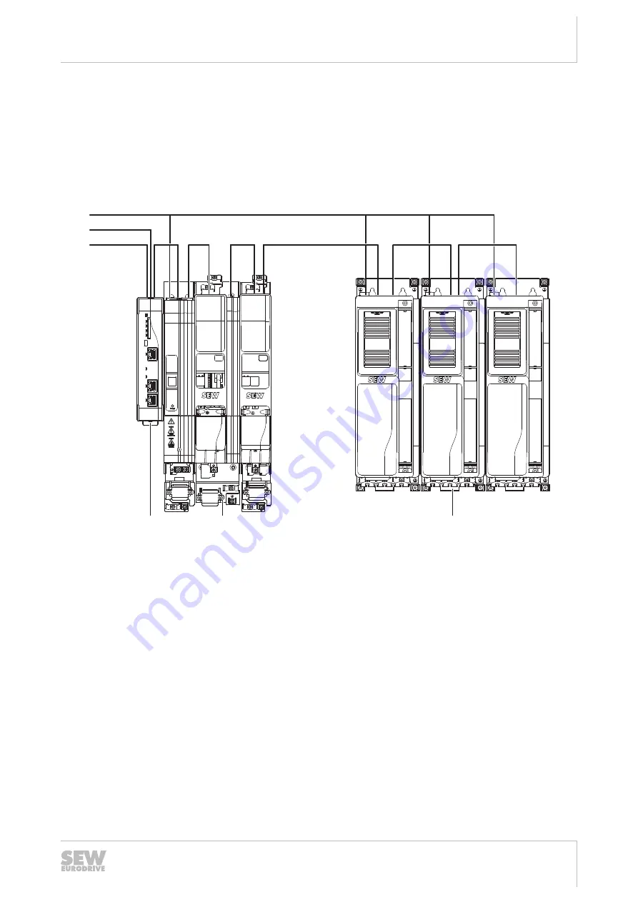
3.2.4
Overview of communication interfaces
The MOVI‑C
®
CONTROLLER has various communication interfaces:
•
The Ethernet communication interfaces allow for engineering purposes for the
MOVI‑C
®
CONTROLLER, for connecting an operator panel as well as for commu-
nication with other Ethernet nodes (e.g. with a PLC).
•
The EtherCAT
®
/SBus
PLUS
interface is used to control drive inverters, I/O modules
and other EtherCAT
®
slave components.
RUN ERR
X15
X2
1
X2
0
X31
S1
S2
+UZ
-UZ
X4
Z
U-
Z
U
+
24V
X5
+UZ
X4
-UZ
-U
Z
+UZ
GND
X31
X20_1
X21_1
X20_2
X21_2
X15_1
X15_2
S1
S2
RUN ERR
+UZ
X4
X5
24V
GND
-UZ
Z
U
-
Z
U
+
U H X 2 5 A - N
L/A
L/A
L/A
L4
L3
L2
L1
T1
S3
BF
US1
X41
X40
X80
XM
[1]
[2]
[7]
[5]
[3]
[6]
[4]
20411752075
[1]
Line voltage
[5]
MOVI-C
®
CONTROLLER
[2]
Fieldbus connection
[6]
MOVIDRIVE
®
modular axis system
[3]
Engineering connection
[7]
MOVIDRIVE
®
system
[4]
EtherCAT
®
/SBus
PLUS
connection
25800736/EN – 08/2018