5
Electrical installation
Connecting the motor and encoder system via KK terminal box
Operating Instructions – CM3C63 – 100
62
5.8.5
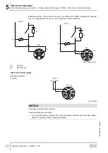
Wiring diagrams of the brake control for BK.. or BZ.D brake
In every application, the BK holding brake can be controlled via the BMV brake relay
or a customer relay with varistor overvoltage protection.
If the system complies with the specifications for direct brake control, then a BK..
brake can also be controlled directly via the brake output of a servo inverter by
SEW‑EURODRIVE.
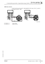
BMV brake control unit – CM3C63
BMV
1
2
3
4
13
14
15
K12
+
-
24 V
DC
24 V
DC
1
2
3
4
5
6
7
8
9
10
5a
4a
U
V
W
PE
9007202156696971
Connection 1, 2
Power supply
Connection 3, 4
Signal (inverter)
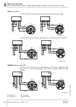
BS braking contactor – CM3C63
1
2
3
4
5
6
7
8
9
10
5a
4a
U
V
W
PE
24 V
DC
- +
BS
1
2
3
4
5
9007202156702347
26870460/EN – 05/2021


