5
Electrical installation
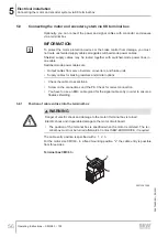
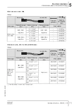
Connecting the motor and encoder system via KK terminal box
Operating Instructions – CM3C63 – 100
59
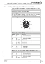
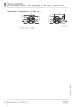
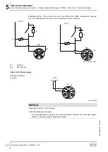
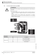
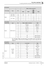
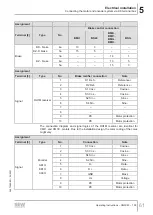
Assignment
Terminal [2]
Type
No.
Brake control connection
BMV..
BS24
BME..,
BMP..,
BMH..,
BMK..
BSG..
Brake
BK.. brake
BZ..D brake
4a
13
3
–
–
5a
15
5
–
–
BZ.. brake
3a
–
–
14
1
4a
–
–
13
5
5a
–
–
15
3
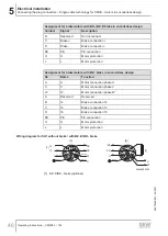
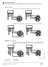
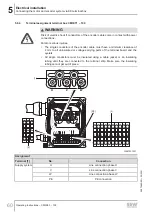
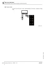
Assignment
Terminal [3]
Type
No.
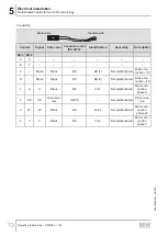
Brake rectifier connection
Note
Signal
RH1M resolver
1
R1 Ref +
Ref
2
R2 Ref -
Reference -
3
S1 Cos +
4
S3 Cos -
Cosine -
5
S2 Sin +
Sine +
6
S4 Sin -
Sine -
7
–
–
8
–
–
9
PK
Motor protection
10
PK
Motor protection
The connection diagram and signal logics of the RH1M resolver are identical for
CMP.. and CM3C.. motors. Due to the installation design, the color coding of the cores
might vary.
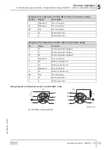
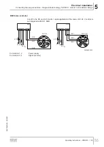
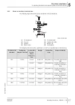
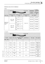
Assignment
Terminal [3]
Type
No.
Connection
Note
Signal
Encoder
AK1H
EK1H
AK0H
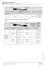
1
cos +
2
ref cos
Reference
3
sin+
Sine
4
ref sin -
Reference
5
D -
DATA
6
D +
DATA
7
GND
Mass
8
Us
Voltage
9
PK
Motor protection
10
PK
Motor protection
26870460/EN – 05/2021

