5
Electrical installation
Connecting the plug connector - Two-cable technology
Operating Instructions – CM3C63 – 100
37
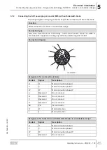
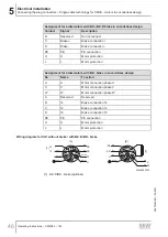
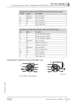
Assignment for motor with AK0H / AK1H / EK1H encoder
Contact
Signal
Description
6
S4 Sin -
Sine -
7
D -
Data -
8
D +
Data +
9
PK
Motor protection
10
PK
Motor protection
11
GND
Protective earth
12
US
Voltage
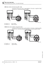
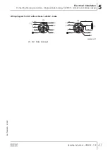
Wiring diagram for signal plug connectors RH1M resolver
INFORMATION
The connection diagram and signal logics of the RH1M resolver are identical for
CMP.. and CM3C motors. Due to the installation design, the color coding of the cores
might vary.
Wiring diagram
Connect the shield to the metal housing of the connector. The color code corresponds
to the cables from SEW‑EURODRIVE.
1
9
8
2
10
12
7
3
4
5
6
11
GY
RD
BU
BNVT
YE
GN
PK
WHBK
S2 (sine +)
S4 (sine -)
1
9
8
2
10
12
7
3
4
5
6
11
BKWH
RD
YE
BU
R1 (ref)
RDWH
BK
R2 (reference -)
S1 ()
S3 (cosine -)
]
B
[
]
A
[
PK
BK
PK
RD
18014427791655691
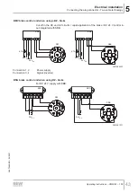
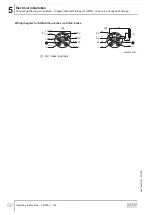
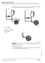
Wiring diagram for signal plug connector AAK0H, AK1H, EK1H encoder
Wiring diagram
Connect the shield to the metal housing of the connector. The color code corresponds
to the cables from SEW‑EURODRIVE.
1
9
8
2
10
12
7
3
4
5
6
11
GN
RD
BU
BN
RDBU; GY
YE
VT
WH
GYPK; PK
BK
BU
1
9
8
2
10
12
7
3
4
5
6
11
RD
GN
YE
S2 (sine +)
S4 (sine -)
S1 ()
S3 (cosine -)
BK
RD
GY
D +
Us
PK
GND
]
B
[
]
A
[
PK
PK
BK
D -
VT
29282171275
26870460/EN – 05/2021


