5
Electrical installation
Connecting the plug connector - Two-cable technology
Operating Instructions – CM3C63 – 100
32
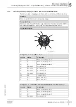
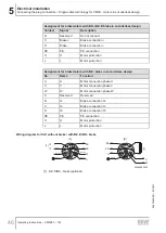
Assignment for motor without brake
Contact
Signal
Description
4
V
Motor connection phase V
Assignment for brakemotors with BK.. brake
Contact
Signal
Description
A
Reserved
Do not connect
B
Reserved
Do not connect
C
Brake +
BK brake +
D
Brake -
BK brake -
PE
PE
PE connection
1
U
Motor connection phase U
3
W
Motor connection phase W
4
V
Motor connection phase V
Assignment for brakemotors with BZ../BZ..D brake
Contact
Signal
Description
A
Reserved
Do not connect
B
Brake
BZ.. brake (omitted for BZ..
D
brake)
C
Brake +
BZ brake +
D
Brake -
BZ brake -
PE
PE
PE connection
1
U
Motor connection phase U
3
W
Motor connection phase W
4
V
Motor connection phase V
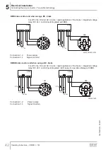
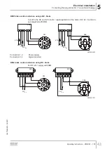
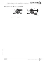
Wiring diagram SM1./SB1. with/without BK.. brake
Connect the shield to the metal housing of the connector. The color code corresponds
to the cables from SEW‑EURODRIVE.
D
C
B
A
3
1
4
BU-
RD+
BU
GNYE
RD
BK
U1
V1
[1]
D
C
B
A
3
1
4
BK (1)
BK
GNYE
BK
BK
+/
U
V
W
-/
BK (3)
[1] [A]
W1
[B]
15
13
[2]
9007228536926859
[1]
BK.. brake (optional)
[2]
Connection to rectifier from SEW‑EURODRIVE according to operating instructions.
26870460/EN – 05/2021


