background image


Doc No. 006-0211-00 Rev AD 


Page 42 of 62 

3.  Connect the other end of the USB cable to an available USB port on your 

computer. 

4.  If this is the first time to plug in the SPS-1500, you may need to install drivers 

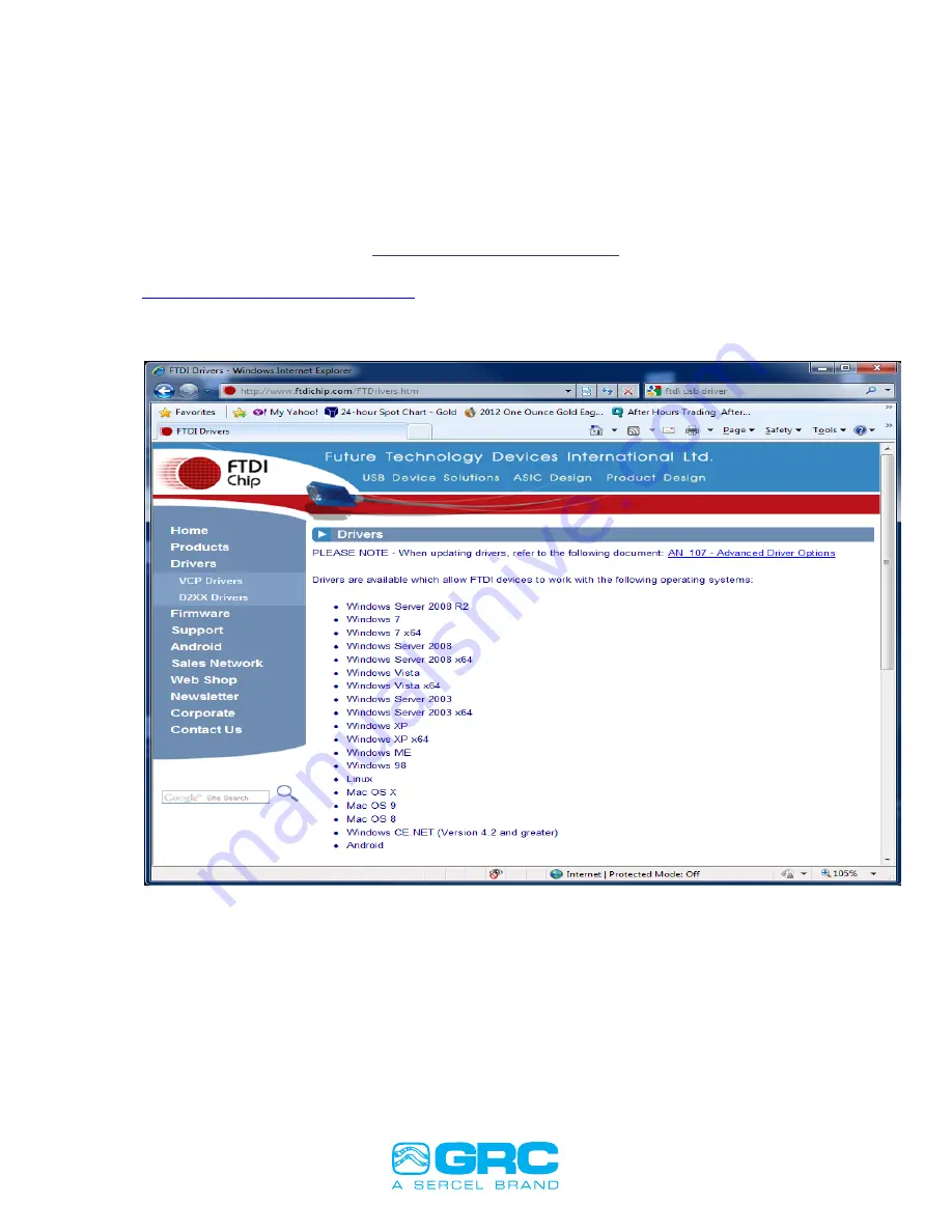
(SEE SCOUT-3000 USB SERIAL DRIVER SECTION BELOW in Figure 
38).  Windows should try to automatically install drivers.  If this fails, please 
contact Sercel-GRC Customer Service at (918) 834-9600 for assistance.  


Figure 38. Scout-3000 USB Serial Driver Installation. 


5.  Start the HyperTerminal software using the "Launch HyperTerminal" button or by 

selecting it in the Start menu. 

6.  Click on the Properties icon in the HyperTerminal toolbar (on the far right). 
7.  In the Properties dialog select the new COM port from the "Connect using" drop 

down menu. 

8.  Click the "Configure..." button and set the port settings to: 
9.  Bits per second=9600, Data bits=8, Parity=None, Stop bits=1, Flow control=None 


SCOUT 3000 USB SERIAL DRIVER 


Go to: 

http://www.ftdichip.com/FTDrivers.htm


Select the Operating System that matches the PC you are using. Normally, when the Scout is connected 
to a PC that is connected to the internet, the PC will automatically download the appropriate driver from 
the site. 


Summary of Contents for GRC ESP Series

Page 1: ... ESP Monitoring System 0 12 11 3 1 ...

Page 2: ... or distributed transmitted transcribed stored in a retrieval system or translated into any human or computer language in any form or by any means electronic magnetic manual or otherwise or disclosed to third parties without the express written permission of Sercel GRC Corp Any questions concerning the content of this manual equipment operation field maintenance maintenance assistance and operatio...

Page 3: ...ACE CHOKE 23 Surface Choke 26 Surge Panel Protector Suppressor 23 Surface Choke and Surge Protector Panel Assembly 90B2175 25 SCOUT 3000 RELAY ALARMS SETUP 28 SOFTWARE AND FIRMWARE INSTALLATION AND UPDATES 28 Scout 3000 for Rev A Only 30 Updating SPS Firmware Using Tera Term TTermpro 30 Updating LCD Firmware 32 Scout 3000 for Rev B and Later Versions 40 Updating RCM Firmware with Memory Tools USB ...

Page 4: ...ENDIX 57 Surface Readout Status Message Summary 57 Fortress ESP Monitoring System Field Checklist 58 ESP Gauge and Surface Control Interface Diagram 59 Surface Readout Devices Gauge Interface Specifications 60 SPS 3000 60 SPS 1500 60 Scout 3000 61 Datalogger 2000 62 ...

Page 5: ...ce Support If any assistance is needed please contact any of our service centers listed below The engineers and technicians will be more than happy to provide you with any assistance needed SITE LOCATION PHONE CAPABILITIES Tulsa OK USA 6540 E Apache Street Tulsa OK 74115 USA 1 918 834 9600 Headquarters Engineering Manufacturing Sales Service for USA and Canada Villahermosa Mexico Comalcalco Num 11...

Page 6: ... body of the sensor as shown in Figure 1 b 6 This next step is applicable to all FORTRESS ESP Sensors EXCEPT the ESP 1800 and where the motor temperature sensor Resistance Temperature Detector RTD is not factory installed 7 Locate the RTD kit Probe Style or Threaded Style 8 Locate the two white wires exiting the top of gauge 9 Temporarily connect the two RTD wires to the two white wires exiting th...

Page 7: ...Doc No 006 0211 00 Rev AD Page 7 of 62 a b HOCKEY PUCK Figure 1 Fortress ESP Wiring Configuration Figure 1A Fortress ESP Wiring Configuration ...

Page 8: ...r supply will be needed Do not set the SCOUT on the Spooling unit as shown on this trailer ONLY CONDUCT THIS CHECK WHILE THE SPOOL IS NOT MOVING NEVER AT ANY TIME STEP OVER THE 3 PHASE ESP CABLE 1 Connect the red wire gauge signal wire to one of the 3 phase leads 2 Connect the white or black wire ground to the shielding on the 3 phase cable 3 Power on the SCOUT 4 Record the parameter readings on t...

Page 9: ...sor so that the three female connections on the Hockey puck are aligned with the three pins coming out of the motor and the holes on the motor base are aligned with the holes on the motor head as shown in Figure 2 Figure 2 Aligning the motor pins to the Hockey puck 2 Carefully stab the sensor onto the motor watching closely that the three pins mate up with the three female connections on the hocke...

Page 10: ...l and plug valve on the gauge and use the one located on the motor Below is a description of the plug Item Part Number Description 1 089 0252 00 PLUG VENT DRAIN 2 089 0254 00 GASKET VENT DRAIN LEAD SEAL 3 089 0251 00 VALVE DRAIN FILL 4 089 0253 00 GASKET LEAD SEAL Note Both gaskets listed above are single use components Item 3 valve should be torqued to 210 in lbs and Item 1 plug should be torque ...

Page 11: ...rt must be purged with motor oil vent plugged and connected to the hydraulic tubing connecting to the pump discharge sub before being deployed Failure to install the Discharge Bleed Plug will result in failure to read the discharge pressure See Installation and Troubleshooting guide for instruction to purge discharge pressure port connections Figure 5 Discharge tubing connection Compression Fittin...

Page 12: ...rge pressure bleed port 9 Remove pressure test system and install plug in port 10 Fill the line with hydraulic fluid until fluid exits the pressure bleed port 11 RIH BHA and tighten the pressure fitting on the discharge pressure port 12 POOH BHA and remove plug from port 13 Immediately install the pressure test system and pressure test to 5Kpsi for 10 min 14 If the pressure remains constant 20 psi...

Page 13: ...Placing the RTD inside the motor oil passages provides faster response times to temperature changes but runs the risk of contacting rotating parts b Shorten the two wires coming from the gauge for the RTD to match where you have determined to place the RTD If it s going inside the motor oil passage secure the wiring and its excess to insure that the RTD is not drawn further into the oil passage by...

Page 14: ... other from the gauge g Slide the heat shrink tubing down over each individual soldered bare wire and heat shrink the two pieces of tubing using a hot air gun heat gun The solder joint should be located in the center of the length of the tubing and the result should appear as shown in Figure 7 h From step c now slide the longer piece of heat shrink tubing over both wires so that the solder joint i...

Page 15: ...ow is the GRC procedure that is used when Manufacturing is attaching the wye point Purpose The purpose of this procedure is to give instructions on how to solder the communication wire to the WYE terminal for ESP gauges Cautions and Warnings Ensure there are no nicks on the conductor of the communication wire when stripping Ensure there are no sharp edges on solder joint of wire and terminal Ensur...

Page 16: ...m the choke is white Fold the excess wire back towards itself making a loop Refer to Figure 52 Figure 9 WYE Connector Shown with the Communication Wire Prior to Crimping Any excess wire extending beyond the insulation of the wire should be removed Before soldering gently crimp the wires with needle nose pliers to close the gap of the wire loop Refer to Figure 10 Figure 10 WYE Terminal Shown with t...

Page 17: ...ide the clear plastic wire insulator to the solder joint Refer to Fig 11 Figure 11 WYE Terminal Shown with the Communication Wire Soldered Slide one piece of heat shrink tubing down to the hex base of the terminal Apply heat to shrink the first heat shrink tubing before applying second layer of heat shrink tubing Refer to Figure 12 Figure 12 WYE Connector Shown with the First Heat Shrink Tubing Un...

Page 18: ...he threaded pin This will go over the first heat shrink tubing Refer to Fig 13a Figure 13 WYE Connector Shown with the Second Heat Shrink Tubing Apply heat to the heat shrink to complete the assembly Refer to Fig 13b for final assembly Figure 13b WYE Connector Terminal Shown with Both Heat Shrink Tubing Shrunk ...

Page 19: ...ly dangerous voltages present INSTALLING THE SURFACE INTERFACE EQUIPMENT SCOUT 3000 Installation Figure 14 shows a typical wiring and installation schematic for the ESP surface equipment Figure 15 describes the specific connections of a Scout 3000 to a gauge Connections are also detailed for the 4 20mA Current Loop and Modbus Figure 14 SCOUT and Suface System Wiring Diagram ...

Page 20: ... Loop Modbus Blue Violet Connect to Pins 1 and 4 Figure 15 Scout 3000 Wiring and Connections SPS 3000 Installation The connections for the SPS 3000 are shown in Figure 16 below Gauge Connection to ESP gauge signal Connection to dedicated wellhead ground VDC Connections to a 12 to 18VDC and Ground ModBus TR and TR Connections to ModBus master Figure 16 SPS 3000 Connections SPS 3000 Sig Grd 12 18V G...

Page 21: ...se 100mA fast acting 5x20mm GRC P N 043 0042 00 Gauge Comm Bi Color LED Flashes green for every gauge data bit received Flashes orange for every gauge data byte received Power Gauge Connections 1 Gauge Signal 2 Gauge Signal Return Wellhead Ground 3 Vdc Ground 4 Vdc Power 12V to 28V DC RS 485 RS422 Modbus Slave RS 485 Install 2 Jumpers RS 422 Remove 2 Jumpers 1 TR 1 T 2 TR 2 T 3 TR 3 R 4 TR 4 R Pow...

Page 22: ...1 00 Rev AD Page 22 of 62 SCOUT 2200 Installation For installations using a SCOUT 2200 ESP Surface Monitoring System the installation and operations manual can be found on the Sercel GRC website at www sercel grc com ...

Page 23: ... Equipment via the gauge signal and wellhead ground Surface Choke The surface choke shown in Figures 18a b is connected between the VSD 3 phase power and the Surge Panel or Surge Protector The purpose of the surface choke is to allow the ESP Gauge Interface to provide power to and communicate with the downhole tool The ESP Gauge Interface provides between 30 80VDC to the Neutral wire on the Surfac...

Page 24: ...ssor The Surge Panel provides protection for the ESP Surface Interface equipment from several failures including overvoltage from imbalance transient voltage pulses and switching spikes Figure 19a Surge Protector Photo User Replaceable 1 2A HV Fuse User Replaceable MOV Recommended replacement anytime fuse is replaced ...

Page 25: ...thing is good downhole and the rig crew can proceed with their rig down 2 Record the parameter readings on the Fortress ESP Sensor Checklist 3 Mount the Surface Choke and Surge Protector Suppressor inside the transformer cabinet 4 Reference Figures 18 19 to see the electrical connections Surface Choke Tips 1 Make sure that the Surface Choke wires that are connected to the transformer are braided 2...

Page 26: ...AD Page 26 of 62 Surface Choke and Surge Protector Panel Assembly 90B2175 Figure 20 Combined Surge Protector and Surface Choke Panel Surge Protector Assembly Surface Choke Interface to motor power cable 3 Phase Fuse Assembly ...

Page 27: ...v AD Page 27 of 62 Figure 21 Surface Choke and Surge Protector Wiring Diagram Surface Interface Connection to Scout or SPS 1500 Red Gauge Signal Black Gauge Ground Motor Wire Connection Green WHG Wellhead Ground Phase A B C ...

Page 28: ... and the current sensor value for each alarm trigger are displayed in the Relay Setup menu Figure 22 If the alarm threshold is exceeded the sensor value will be displayed in red with time remaining until the alarm is enabled To enable an alarm press the Edit Relay button to select the triggers from the Relay Edit Menu shown in Figure 23 Enable the desired triggers by pressing 1 6 on the menu to se...

Page 29: ...lay board is installed as an option the relay contacts close A 5 second alarm is sounded on the Scout 3000 the volume is the same as is set in the Display Sound menu The event is recorded to the USB thumb drive in a file called ALARMLOG CSV The file is appended with one line in a comma separated text format showing the information about the alarm An example of one trip event in the file is TripTim...

Page 30: ...cedure 1 Use USB A B cable between computer and TTL converter 2 Attach TTL converter to J3 small ribbon cable is located on this header 3 Open TTERMPRO 4 Select SERIAL BUTTON 5 DROP DOWN BOX and SELECT USB SERIAL PORT See Figure 26 Figure 26 Select USB Serial Port 6 OK 7 SETUP MENU then SERIAL PORT to check the SERIAL PORT SETTINGS See Figure 27 a PORT Select Com Port b DATA 8 Bit c PARITY NONE d ...

Page 31: ...d power up the Scout 3000 10 FILE TRANSFER XMODEM SEND 11 Screen shows BEGIN TRANSFER and C 12 Select file MODBUS 32 BIN from whatever location you have it stored in and DOUBLECLICK 13 File begins transferring See Figure 28 Figure 28 Files transferring 14 File transfer is completed See Figure 29 ...

Page 32: ...ating LCD Firmware Parts Required 1 USB Cable Type A to Type B Mini 2 BMPLoad software 3 Latest firmware version 90A2330 for the Scout 3000 SLCD_Firmwarexx FWU Procedure 1 Remove the Scout 3000 front panel 2 Disconnect the wiring harnesses from J1 and J2 across the top of the back side of the LCD 3 Plug USB Type B Mini cable from PC to J3 Mini USB socket on the left side of the LCD 4 Open the scre...

Page 33: ...006 0211 00 Rev AD Page 33 of 62 Figure 30 BMPLoad Software 5 Select the Comm Port associated with the USB connection 6 Change the Baud Rate to 460800 7 Click Connect Select Comm port Change Baud Rate Connect ...

Page 34: ... Figure 31 BMPLoad software checking the SLCD status 8 Verify SLCD Status shows Connected 9 Click Load from File and the Open screen will appear change the file type to Combined Upgrade FWU See Figure 32a SLCD Status Message Load File Button ...

Page 35: ...nging the file type 10 Select Firmware file Scout 3000 SLCD_Firmwarexx FWU and click Open See Figure 32b Figure 32b Selecting the right firmware for the Scout 3000 Change File Type to Combined Upgrade FWU Select Firmware file Scout 3000 SLCD_Firmwarexx FWU ...

Page 36: ...dy to be transferred Click OK 12 Click Store into SLCD to begin transferring the file to the LCD See Figure 33 The SLCD status screen will indicate the file transfer as shown in Figure 34 Figure 33 Transferring the firmware for the LCD Click Store into SLCD to begin transferring the firmware to the LCD ...

Page 37: ...Doc No 006 0211 00 Rev AD Page 37 of 62 Figure 34 SLCD status screen indicating the LCD file transfer The SLCD Status screen will indicate the file transfer ...

Page 38: ...1 00 Rev AD Page 38 of 62 13 After the file is prepared for transfer the software will ask to calibrate the screen Click No as shown in Figure 35 Figure 35 Do not calibrate the touch screen Calibrate Touch Screen NO ...

Page 39: ...Quit to exit the program See Figure 36 Figure 36 Final screen showing that the program was transferred successfully 15 Disconnect the USB Cable from the LCD and reattach the wiring harnesses to the LCD ports and close the front panel SLCD Status screen will show the program was successfully transferred Click Quit ...

Page 40: ... using Baud Rate 115200 Parity NONE Data Bits 8 and Stop Bits 1 Click APPLY 5 Go to PREFERENCES then to PROGRAM MODE and pick DIAGNOSTIC 6 Enter password XGRCService 7 Select REAL TIME from the tool bar 8 Select RCM UPGRADE button at bottom of screen 9 Select the location that Scout 3000 RCM Firmware xx bin is located at and then select OPEN 10 Follow the screen prompts NOTE SCOUT 3000 RCM UPDATE ...

Page 41: ...herever it has been stored Standard is SCOUT 3000 RCM Firmware xx bin 13 Some GE installations use SCOUT 3000 RCM Firmware 20ggemodbus bin for use with the Vector 7 drive running the basic program SPS 1500 Updating SPS 1500 Firmware Using Hyper Terminal Utility Parts Required 1 USB Cable A B P N 136 0076 01 2 Computer with Hyper Terminal software 3 Current released version of SPS 1500 firmware 4 P...

Page 42: ...Terminal software using the Launch HyperTerminal button or by selecting it in the Start menu 6 Click on the Properties icon in the HyperTerminal toolbar on the far right 7 In the Properties dialog select the new COM port from the Connect using drop down menu 8 Click the Configure button and set the port settings to 9 Bits per second 9600 Data bits 8 Parity None Stop bits 1 Flow control None SCOUT ...

Page 43: ...S 1500 and repeat this step 11 Select Send file from the Transfer option on the HyperTerminal menu bar 12 In the dialog box that opens select the file that contains the SPS 1500 firmware set the protocol to X modem and press Send 13 When the transfer is complete remove power from the SPS 1500 disconnect the USB cable and reconnect the RS 485 interface 14 Power the SPS 1500 back on and verify the n...

Page 44: ...L PORT and COM PORT NUMBER found under CONTROL PANEL DEVICE MANAGER PORTS 4 OK 5 SETUP MENU then SERIAL PORT See Figure 39 a PORT Select Com Port b Baud Rate 9600 c DATA 8 Bit d PARITY NONE e STOP 1 BIT f FLOW CONTROL NONE 6 Select OK Figure 39 TTERMPRO Serial Port Setup 7 Depress SHIFT U while powering up the SPS 1500 You should see the screen in Figure 40 ...

Page 45: ...ion and choose 90A3141 MODBUS SPS 1500 to open location 10 Select SPS 1500_20g BIN and then click OPEN which will begin transfer as shown in Figure 41 Figure 41 Transferring firmware file 11 Screen will say TRANSFER COMPLETE when done 12 Power the SPS 1500 off and then back on and you will see the firmware version on the display ...

Page 46: ...ile then click on SAVE 4 Click YES then SAVE 5 To see the Well Test Data 6 Click the WELL TEST DATA tab 7 Click on OUTPUT FORMAT box choose the format that you would like to see 8 To Export Data in Excel Format 9 Click on FILES 10 Click on EXPORT 11 Choose CSV ASCII 12 Check HEADER and COLUMN box 13 Click on SAVE FORMAT and choose the one you like 14 Click on SAVE 15 Create a file name 16 Click on...

Page 47: ... 1 Install a 4 20 mA card 99B470 into J8 4 20 mA connector on the Scout mother board and secure it with the standoff included in kit as shown in Figures 43 44 Figure 43 4 20 mA module 4 20mA Current Loop Module Connection SPS Module Gauge Power Supply Gauge Signal and Signal Return Connections 4 20mA Current Loop Module Connection AC Power Input Connection Graphing Memory Backup Battery Earth Grou...

Page 48: ... Wire 4 20 mA current loop with power supply Figure 46 Figure 46 4 Install Relay card and secure with 4 40 screw provided Figure 47 Figure 47 Screw position 4 20mA Switch position Install standoff here 4 20 mA Receiver Install screw here If a second 4 20 mA card is installed the upper card will have this switch in the opposite position The lower card will have the switch in the position shown ...

Page 49: ...tch position on relay card 6 Connect the signal wires to the relay card as shown below Figure 49 Signal wires connection 7 Configure the Analog Card and Relay Card in the Scout Ports menu as detailed below The Ports menu is under the Menu tab on the Scout 3000 Home Screen Relay Switch position Normally Closed contact Normally Open contact Common contact ...

Page 50: ...d low trip alarm points on the 4 20 mA current loops In this example a reading under 5 0 PSI or above 5050 0 PSI will trip the alarm For example you could setup a SCADA system to turn the motor off if 12 0 mA current is received which could represent a particular intake pressure Note The 4 20 mA current loops can actually output 0 to 24 mA so this alarm current could be set outside the 4 20 mA ran...

Page 51: ...e isolated from the rest of the circuit while checking this will prevent a false reading b MOV should read infinite in both directions when checked with a multimeter c Fuses should check less than 2 ohms except for the fuse in the Scout 3000 which will read approximately 12 ohms d Surface Choke should read approximately 260 ohms phase to phase and 130 ohms phase to neutral wire 5 Depending on the ...

Page 52: ...ally set the operating parameters Turn off the Auto Volt and Auto Analyzer and begin stepping the voltage from 40 V to 80 V to see if that doesn t solve the problem The SPS is susceptible to faults caused by phase imbalances that can result in AC voltage at the gauge signal connection point Phase imbalance voltages can result in tool communication problems In addition if the voltages at the gauge ...

Page 53: ...age 53 of 62 Figure 51 Scout 3000 Main Display Select SPS Menu Figure 52 Scout 3000 System Menu Select Operation Settings Figure 53 Scout 3000 SPS Setup Menu Select Set Voltage to change the SPS voltage Select Operation Settings ...

Page 54: ...peat the above process incrementing the voltage by 4 volts Continue repeating this process until the Scout is reading the gauge data It will take around 12 minutes to begin receiving tool data As it is acquiring data the LCD screen will read a series of headers Hdr 1 through Hdr 13 after Hdr 12 it will show the Serial of the tool After Hdr 13 it will show the pressure and temperature data Figure 5...

Page 55: ...s such as High Amp Low Amp DC to DC Bad Analyze 1 through Analyze 16 as well as other normal messages that are all part of acquiring the tool After the Scout analyzes the line current from the tool you will see the message SPS Power OFF a couple of times and then it will go through 2 or 3 phase Sync packages and then begin to get header data This is all part of normal operations of the SPS 1500 Th...

Page 56: ...NO SIGNAL Gauge is potentially not working or bad connection Check at wellhead with portable Scout 3000 Check wiring between wellhead and Scout 3000 BAUD SLOW BAUD FAST BAUD NOISY NO SYNC BREAK Bad ground phase imbalance Installation problem locked on something besides the gauge bad ground phase imbalance Check motor drive ground problems HdrPACKET XSUM Incorrect gauge voltage In manual mode incre...

Page 57: ... SPS SncPhs 2 Initial Current Check SPS SncPhs 3 Detecting 1st Signal Transition SPS SncPhs 4 Measuring Tool Signal SPS SncPhs 5 Wait for End of Sync Phase SPS Power Off Gauge Power Off SPS Init EE Initialization Rcv Hdr nn Receiving Tool Header Rcv Dat mm Receiving Tool Data Analyze 1 16 Analyzer Config Coils Initialization Driving HighV Safe Volt Disabled and Driving Imbalance ...

Page 58: ...ESP SENSOR READING CUSTOMER WELL OPERATOR WELL NAME CK 10 120 STANDS IN HOLE ESP SENSOR READING CK 11 FINAL STAND IN HOLE ESP SENSOR READING CH 12 END OF SPOOL AT JUN BOX ESP SENSOR READING CH 7 60 STANDS IN HOLE ESP SENSOR READING CK 8 90 STANDS IN HOLE ESP SENSOR READING CK 9 100 STANDS IN HOLE ESP SENSOR READING CONTIN PIN 2 4 ESP SENSOR SURGE SUPPRESSOR 3 PHASE SURFACE CHOKE LOADOUT FUSE INTEG...

Page 59: ...or Analog communication 15 VDC Earth Ground Gauge Signal Gauge Ground Surge Panel Well Head Ground Gauge Signal Y point Surface Choke Motor and Pump Choke and Sensor Line Service Transformer Power Source 3 Phase Motor Cable Or AC for Scout Motor Head Adapter and WYE Step Up Transformer Figure 56 ESP System Diagram ESP Downhole Choke and Sensor Module Gauge Pressure Measurement The intake pressure ...

Page 60: ...Low cost dust proof enclosure Single ESP gauge interface Modbus communication via RS485 RS 232 RS422 12 24VDC power required 200mA Configurable via free Memory Tools software Operating Temperature 10ºC to 70ºC SPS 1500 Specifications Small footprint DIN rail mount enclosure Enclosure size 3 1 2 x 3 1 2 x 2 1 2 2 Line LCD display with scrolling update of downhole sensor data 2 Multi color displays ...

Page 61: ... trending data may be viewed in for periods of hours to 42 days Figure 59 Scout 3000 Scout 3000 Specifications NEMA 4X Enclosure with clear latching cover Single ESP gauge fused interface Removable 8G USB Memory Storage of well data Front Panel USB connection for PC monitoring and configuration Power Requirement 110 220 VAC or 12 24VDC Configurable via Touch Screen display Graphic Data trending di...

Page 62: ...monitoring of any parameters Figure 60 Datalogger 2000 Datalogger 2000 Specifications NEMA 4X Enclosure Single SPS 3000 gauge interface RTU Internal 4 Line Character LCD display 2 GB Internal removable logging memory 8 Analog Outputs 16 Analog Inputs 9 Relay Outputs 16 Digital Inputs 4 20mA mA in and out Modbus master RS485 RS 232 Modbus slave RS 485 RS 232 USB Baud rate 1200 to 38400 110 220 VAC ...

Page 63: ...suring recording and delivering reliable and accurate well data with extremely high resolutions Sercel GRC provides gauges and surface readout tools for permanent memory mechanical and artificial lift applications and is the manufacturer of the Amerada mechanical gauge used for over 80 years in the oil and gas industry For more information on this product or any of the qual ity monitoring and data...

Reviews: