


Senstar LM100 calibration
Senstar LM100 Product Guide
Page 61
Verifying the luminaire segment boundaries
1.
Establish a UCM connection to the LM100 gateway and select the Config tab.
2.
Select File > Response Plot and set the Senstar LM100 response plot so the Display Format is
Magnitude vs Location, the Heads: All radio button is selected, and the Peak Capture
checkbox is selected.
3.
Select the Record button to start the plot.
4.
Have the tester tap the fence post of the luminaire that is defined as the start point of the
second segment with the blade of a screwdriver (or similar object). Use consistent force and
tap 3 times waiting 2 seconds between each tap.
5.
On the UCM, verify that the alarm was reported by the luminaire defined as the second
segment’s start boundary.
6.
Move along and continue tapping fence posts to mark the start points of the designated
segment boundaries.
Setting the Threshold
The Threshold represents the received signal strength at which the Event Count is incremented.
An independent Threshold can be set for each of the defined segments. Thresholds can be
adjusted for any high risk or low threat areas, as well as any areas that may be subject to a higher
nuisance alarm rate (NAR) such as an open stretch of fence that is regularly exposed to strong
winds. The Threshold can also be used to disable alarm detection in a segment by setting the
Threshold to the maximum value of 254. Reducing the Threshold in high risk areas will increase
the Pd in that area. However, a lower Threshold setting may increase the nuisance alarm rate. For
an area where the threat is considered low, increasing the Threshold will reduce the chance of
nuisance alarms occurring while still providing an acceptable probability of detection (Pd).
Note
Senstar recommends marking a site plan (or a table) with numbered
luminaire locations, the segments to which the luminaires are assigned
and the alarm zones to which the luminaire segments are assigned.
The initial segment begins with luminaire 1 (by default).
Note
You can use the indicate button to identify boundary locations by
activating the head that represents the boundary. Select the head then
select the indicate button. The selected head will flash 5 times.
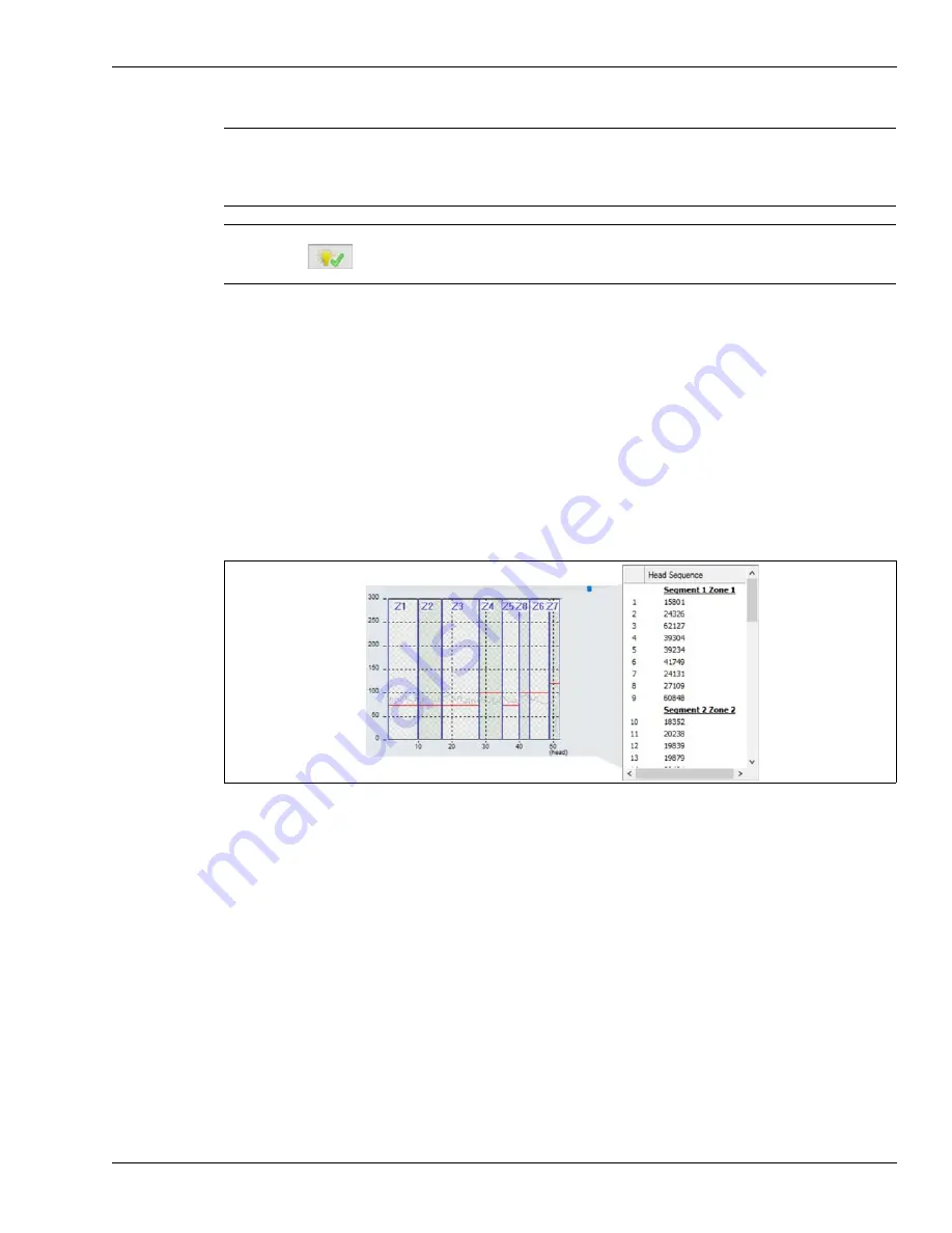
Figure 56: Segment and zone assignments on the Head Sequence window


