


The Universal Configuration Module
Page 46
Senstar LM100 Product Guide
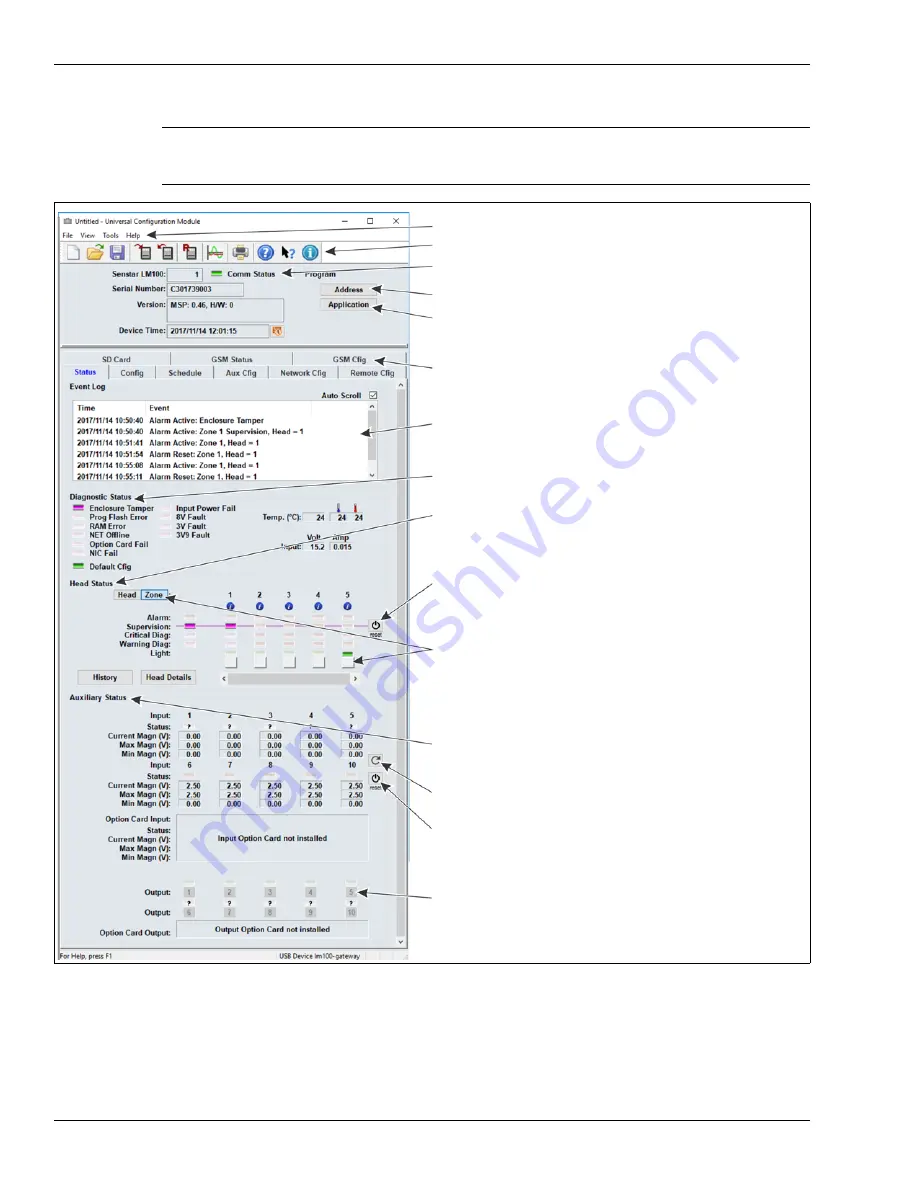
When you select the Connect button, the UCM status window displays.
The following table includes the Senstar LM100 configuration parameters along with a brief
description of each parameter. The Sensor Head Configuration settings apply to all of the installed
luminaires, unless the parameter is assigned to a specific segment or zone.
Note
Refer to the UCM help file and the appropriate section in this document
for additional details on configuring the Senstar LM100 and UCM
operation.
Figure 49: UCM Status window
UCM menu selections
UCM fast access buttons
details about the connected gateway
(green Comm Status Led indicates active UCM connection)
select Address to set the gateway’s Silver Network address
select Application to update the gateway, luminaire, or wireless gate
select a UCM tab to display and configure the associated properties
the Event Log contains the 500 most recent Events since the UCM
was connected
the Diagnostic Status field displays the results of gateway self-tests
the Head Status field displays information about the luminaires on
the wireless mesh network
the Auxiliary Status field displays information about the gateway’s
use the reset button to set the heads’ supervision to their current
installation locations and orientations
sensor firmware
inputs and outputs
select the refresh button to update the Input Status
select an output identifier to activate the output
use the reset button to set the minimum and maximum voltage
levels to the current level
select the Head button, then select the activate button, to turn on the
select the Zone button, then select the activate button, to turn on the
lights of the selected head; the Light indicator above the activate
lights of all heads assigned to the same Zone
button is green while the lights are on


