Description of boards 19
9) DESCRIPTION OF BOARDS
The following sections illustrate regular work conditions of boards making up the power source, and furnish standard values for
the electrical measurements that can be taken at the main points of said boards.
All measurements indicated can be taken with a digital multimeter.
Remember that testing should always start with a VISUAL INSPECTION!
Visual inspection reduces the time spent troubleshooting and points any subsequent steps in the direction of the dama-
ged part!
Generally speaking, the following points should be inspected visually:
- input filter zone
- DC bulk electrolytic capacitors
- check for traces of fumes on the inside of the cover
- power and signal connections
- overall status of boards.
WARNING!: Unless otherwise specified, before taking measurements described in the following sections, disconnect
HF board 15.14.286 from bus board 15.14.285/15.14.315!
IMPORTANT NOTE! When the machine is connected to the mains, the master switch is live regardless of its status
(open or closed). Consequently, you are recommended to unplug the unit before touching any of the parts inside!
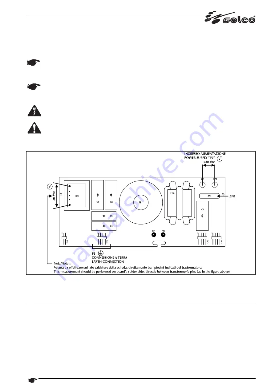
9.1) INPUT FILTER BOARD 15.14.252 (fig. 15)
Filter board 15.14.252 contains a varistor
1
guarding against supply overvoltage, an auxiliary transformer and EMC filter circuitry.
The filter basically consists in a network of capacitors, some earthed, and a shared inductor.
This circuit has the dual purpose of limiting the machine's radiofrequency emissions to levels prescribed by regulations, and
making the power source immune from similar problems caused by any electronic devices connected to the same power supply.
1
A varistor ZN1 is inserted between the two power supply's input phases meaning that if you find an instantaneous voltage over
275Vac between terminals RV1 and RV2, the varistor instantly starts conducting so as to absorb a sufficient current spike to limit
the above-mentioned overvoltage. In this way, varistor ZN1 protects other parts of the machine from overvoltage characterized
by a limited energy content.
This process is actually non-destructive for the component if the energy delivered by the voltage spike is moderate, as is the case
with atmospheric discharges (lighting). If, on the other hand, overvoltage is considerable and prolonged, the varistor cannot dis-
sipate all associated energy and blows.
This happens, for instance, if the machine is accidentally connected to supply voltages over 275Vac, or if it is subjected to over-
voltage caused by inadequate or non-stabilized generating sets.
Unless otherwise specified, all measurements sholud be taken with the boards in their slots and connected accordingly


