background image

76

TROUBLESHOOTING

16

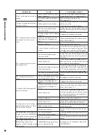
Error 37

DISPLAY 

Verifying Game Program Failed.

CAUSE 

The program image is unveri

fi

 ed due to the program image not existing on 

the game disk or server.

COUNTERMEASURES 

Check that the correct game disk is inserted.

Error 41

DISPLAY 

Server Not Respond.

CAUSE 

The server is not responding.

COUNTERMEASURES 

Check the network settings.


Set IP Address and other settings.


Check that the network cable has not been pulled out.

Error 42

DISPLAY 

Server Mount Failed

CAUSE 

The server directory is could not be reached.

COUNTERMEASURES 

Check the network settings. Set IP Address and other settings.


Check that the network cable has not been pulled out.

Error 43

DISPLAY 

IP Address Not Assigned.

CAUSE 

An IP Address could not be obtained from the DHCP server.

COUNTERMEASURES 

Check the network settings. Set IP Address and other settings.


Check that the network cable has not been pulled out.

Error 44

DISPLAY 

Game Program Not Found on Server.

CAUSE 

No program image on the network server.

COUNTERMEASURES 

Check that the game title, place on the network server, and the key chip 

correspond to each other.

Caution 51

DISPLAY 

Wrong Resolution Setting.

CAUSE 

The game does not support the current resolution settings.

COUNTERMEASURES 

Change the DIP SW to the correct settings and restart.

Caution 52

DISPLAY 

Wrong Horizontal/Vertical Setting.

CAUSE 

The monitor horizontal/vertical settings are incorrect.

COUNTERMEASURES 

Change the DIP SW to the correct settings and restart.

Summary of Contents for Initial D4

Page 1: ......

Page 2: ...d The step may be omitted for products in which a power cord with earth is used Perform work in accordance with the instructions herein stated Instructions for work are explained by paying attention t...

Page 3: ...uld be performed only by those technical personnel who have knowledge of electricity and technical expertise Be sure to adjust the monitor projector properly Applies only to the product with a monitor...

Page 4: ...AMCHINE 4 4 PART DESCRIPTION 5 5 ACCESSORIES 6 6 ASSEMBLY AND INSTALLATION 7 6 1 INSTALLING THE CABINET 8 6 1 1 ATTACHING THE POP 8 6 1 2 SECURING IN PLACE 8 6 1 3 REFILLING THE CARDS 9 6 1 4 CONNECT...

Page 5: ...5 12 1 SWITCH UNIT 45 12 2 SYSTEM TEST MODE 45 12 3 GAME TEST MODE 45 13 MONITOR LCD DISPLAY 59 13 1 SAFETY PRECAUTIONS WHEN HANDLING THE MONITOR 59 13 2 CLEANING THE SCREEN SURFACE 59 13 3 ADJUSTMENT...

Page 6: ...ical cord from the outlet and contact the office listed below or the point of purchase for this product Use of this product is unlikely to cause physical injuries or damage to property However points...

Page 7: ...to be carried out by site maintenance personnel Amusement equipment vending machine assembly maintenance inspection and replacement of units expendable parts Other qualified professionals Persons emp...

Page 8: ...nual is carried out an accident may occur If it is nec essary to carry out work not indicated in this manual be sure to have it done by the office indicated in this manual or by the point of purchase...

Page 9: ...check the Electrical Specifications Ensure that this product is compatible with the location s power sup ply voltage and frequency requirements A plate describing Electrical Specifications is attache...

Page 10: ...custom ers physical conditions It is suggested to ensure a space allowing the players who feel sick while playing the game to take a rest Check if all of the adjusters are in contact with the surface...

Page 11: ...by striking head hand or elbow Persons other than the player should not be allowed to touch the controls during play They may brush against or collide with the controls or the player possibly resultin...

Page 12: ...5 PART DESCRIPTIONS 4 PART DESCRIPTION 4 POP LCD DISPLAY CONTROL PANEL ACCELERATOR AND BRAKE CASHBOX DOOR CARD READER WRITER SHIFT LEVER BILLBOARD PANEL SEAT ASSY COIN DOOR...

Page 13: ...IT LUECO 30SHT 601 11949 1 1 set 30 sheet package NOTE When you order the DVD ROM disc only specify the part number 610 0727 0030 DVD SOFT TFF EXP NOTE We already installed game software in MAIN PCB K...

Page 14: ...ceiling may cause an accident and assembly work to be difficult To perform work safely and avoid serious accident such as the cabinet falling down do not perform work in places where step like grade d...

Page 15: ...y a serious accident may occur 1 Move the product to the installation site See Chapter 2 for examples of installation Ensure that you leave enough aisle space for the player to sit in the seat Additio...

Page 16: ...to malfunction or become damaged Be sure to adhere to the assigned procedures orientation and quantities when loading the cards Loading the cards incorrectly may cause damage to the product or malfun...

Page 17: ...cover then fix it in place with truss screws 3 Refill the Initial D4 IC cards Place the cards in the orientation shown in the diagram loosen them and load 100 cards Do not load more than 101 cards as...

Page 18: ...N cable as bottom slit of cabinet 6 1 4 FIG 01 6 1 5 FIG 02 2 Connect LAN cable connectors to the both LAN connectors One near by USB MINI connectors on both Left and Right cabinet of MAIN PCB After t...

Page 19: ...DVD DRIVE you could suffer vision impairment Do not look inside the DVD DRIVE Do not use or store the DVD DRIVE or DVD wire in any of the following locations as this may result in serious dam age Do n...

Page 20: ...e specifications of such general purpose parts If this is the case SEGA cannot repair or replace a failed kit whether or not a warranty period has expired Handling the DVD ROM Disc Do not use a DVD RO...

Page 21: ...out or return only while the power supply is engaged The tray cannot be opened or closed while the power is off Even after the software has been installed store the DVD software kit DVD DRIVE and DVD...

Page 22: ...D 9 Press the DVD DRIVE switch so that the tray goes back into the unit If the power is cut off the tray will not move 10 Set the main switch to OFF Remove the DVD wire from the DVD DRIVE 3 The LINDBE...

Page 23: ...PUT TEST in the game test mode Check whether or not the speakers are connected and functioning correctly using OUTPUT TEST in the game test mode Adjust STEEERING GAS and BRAKE in INPUT ASSIGNMENTS in...

Page 24: ...e cards may cause the machine to fail Set virgin cards taken out from a container that was unpacked immediately before use Do not include a corrugated bent or used card in the card deck You can refill...

Page 25: ...is turned off and on Insert a cleaning card to IC card RW entry NOTE Cleaning cards can be used up to 3 times However do not use a cleaning card if there is no longer alcohol on the surface if the car...

Page 26: ...W PRINTER TEST Do not select or execute CLEAN STOCKER at this time 2 Carry out steps 1 through 3 in 7 1 Setting Dedicated Cards and remove the cover and raise the retainer 7 2 FIG 04 IC CARD R W PRIN...

Page 27: ...IT STATUS area and change to DONE when complete 7 2 FIG 08 IC CARD R W PRINTER TEST RESET UNIT CHECK CARD CHECK PRINTER CHECK STOCKER CLEAN ROLLER CLEAN STOCKER ERASE PRINT EXIT UNIT STATUS CLEANING S...

Page 28: ...tach the cover This product counts the number of times the game is played When the number of plays exceeds 200 a notice appears on screen the next time the product is turned on requesting that a clean...

Page 29: ...so that game play can be restored exercise extreme caution Machine parts may move unexpectedly when the power is ON This may result in fingers being caught or severed and other injuries 2 Pulling on...

Page 30: ...2 Remove the 2 screws Pull out the card R W unit Since the unit is still wired take extra care as you remove the 2 connectors 7 4 FIG 02 3 After you remove the 2 flat head screws and the cap you can...

Page 31: ...D License is displayed 3 Select RESTORE STATUS will display INSERT THE CARD REQUIRES RESTORING Insert the card with the ACCESS CODE you selected in step 2 as shown in the diagram If the product fails...

Page 32: ...ack records and battle results Your name Character photo style portrait areas cleared and Key are printed on the face of your Initial D License NOTE The Key is necessary when recording results on the...

Page 33: ...Downhill Day Night Clear Rain Hard Irohazaka One Way Downhill Reverse Day Night Clear Rain Expert Tsukuba One Way Outbound Inbound Day Night Clear Rain 8 2 GAME FLOW 1 Advertise Stand by Movie Screens...

Page 34: ...the player name input screen NOTE Your name can be up to 6 characters long 5 Card Data Check Screen You can check the recorded data on this screen NOTE After your first play you can view your battle r...

Page 35: ...ngs Return all settings on the page to their default values 7 Car Selection Screen when playing without an Initial D License adding a new car or adding additional car data Select your car s maker mode...

Page 36: ...ends without the option of continuing in all modes 20 minutes before the store closing time set under CLOSE SETTING or if the CON TINUE setting on the GAME ASSIGNMENTS screen is set to OFF 11 Customi...

Page 37: ...Rival II will appear for the Final Race Beat Secret Rival II and a third hidden character Secret Rival III will appear for a Special Race Finish the Special Race to view the game ending Select Rivals...

Page 38: ...reen which appears after you insert your Initial D License When you set a new personal best in Time Attack mode using an Initial D License an Internet Rankings password is dis played on the screen Vis...

Page 39: ...all the points you ve collected You cannot play using data on an expired Initial D License until you renew the license NOTE Credits money are required to renew a license 8 4 1 FIG 01 Initial D Licens...

Page 40: ...uck Initial D license The removed license is expired Please give it to the customer When finished please close the lid and press the Start button Remove the stuck old Initial D License and make sure t...

Page 41: ...Initial D license This is not a new card 407 Check the license and insert it again If the license fails to renew after 3 tries the screen switches to the normal authentication failure error message a...

Page 42: ...get caught when opening and closing the control panel adjusting the VR bracket or performing other maintenance tasks When securing the plastic made parts do not excessively fasten screws and nuts Fai...

Page 43: ...reful that your hands or feet do not get caught between the panel and game unit Also do not support the steering wheel portion of the panel as this may deform or damage the wheel 9 1 FIG 02 HEX BOLT 4...

Page 44: ...ed to the left the numbers decrease and when it is turned to the right the numbers increase Replacement Procedure When replacing the volume you will also need to prepare three lengths of heat shrinkab...

Page 45: ...ch the connector Close the control panel and secure it 10 Switch on the unit Be careful not to touch the steering wheel when doing so After the unit is switched on the steering wheel undergoes automat...

Page 46: ...ck M6x12 w spring washer 9 4 FIG 02 STOPPER HOLDER TFF 2511 If the start button view change button or the up down left right directional buttons are not working correctly it is possible that the switc...

Page 47: ...ve the four screws and lift the input switch base 9 5 FIG 04 9 5 FIG 05 SCREW 4 M4x10 w flat spring washers INPUT SWITCH BASE 5 Remove the input switch rubber and board 9 5 FIG 06 INPUT SWITCH RUBBER...

Page 48: ...r 10 1 FIG 01 SHIFT LEVER 10 When working with the product be sure to turn the power off Working with the power on may cause an electric shock or short circuit Be careful not to damage the wires Damag...

Page 49: ...washer and spacer Remove the two rubber stoppers 3 Remove the lever shaft bearings crimped spring washer and spacer and detach the shift lever 4 Remove the two tapping screws and detach the knock base...

Page 50: ...m the point of purchase Do not touch the steering wheel when switching the unit on The steering wheel undergoes automatic initialization immediately after the unit is switched on Be sure to perform vo...

Page 51: ...ibed above in Adjusting Procedure see Service Manual 4 When you have finished check that the values change smoothly in response to pedal input 3 Secure the potentiobase Configure the volume values on...

Page 52: ...not described in this text It is possible that the game will not function properly In the SYSTEM TEST MODE LINDBERGH board functioning can be checked the monitor adjusted and the coin setting performe...

Page 53: ...of input devices This test should be used periodically to check that each input device is functioning correctly 12 3 2 INPUT TEST Test the STEERING GAS and BRAKE controls to ensure that they are funct...

Page 54: ...functioning correctly 12 3 3 OUTPUT TEST 12 3 3 FIG 01 OUTPUT TEST START BUTTON OFF VIEW CHANGE BUTTON OFF UP BUTTON OFF DOWN BUTTON OFF RIGHT BUTTON OFF LEFT BUTTON OFF EXIT SELECT WITH SERVICE BUTT...

Page 55: ...STEERING ro tates to the left as far as possible and then stops Press the SERVICE Button again to turn it OFF and release control of the STEERING Move the cursor to EXIT and press the TEST Button to r...

Page 56: ...EERING O CENTER RIGHT LEFT EXIT SELECT WITH SERVICE BUTTON AND PRESS TEST BUTTON GAS ADJUSTMENTS Make adjustments to GAS Press the TEST Button to display the following screen 12 3 5 FIG 03 Set the MAX...

Page 57: ...3 6 GAME ASSIGNMENTS 12 3 6 FIG 01 GAME ASSIGNMENTS ADVERTISE SOUND ON GAME DIFFICULTY NORMAL DEFAULT VIEW DRIVER SEAT NUMBER 1P CARD R W USE ON CONTINUE ON IN STORE VS LIMIT OF WIN 3 TIMES EXIT SELEC...

Page 58: ...IT and press the TEST Button to return to the Game Test Menu Screen Select PASSWARD CONFIRMATION to display the following screen 12 3 7 PASSWORD CONFIRMATION When you receive a password notice from SE...

Page 59: ...mal and has no problems INTERRUPTED CARD The card was interrupted while writing UNKNOWN CARD The card status is unknown DELETE CARD The card is used up BROKEN CARD The card is broken UNKNOWN ID The ID...

Page 60: ...PTY There are no cards in the stocker SENSOR indicates the status of the sensors It displays the status of the card sensors on the card reader writer and printer Select IC CARD RESTORATION to attempt...

Page 61: ...SELECT ACCESS CODE Use the SERVICE Button to move the cursor to this item and press the TEST Button to select an access code NOTE NO DATA is displayed if there are no saved data files 12 3 10 NETWORK...

Page 62: ...SE SETTING disables card play from 20 minutes prior to the designated time until 7 00 AM The screen displays store closing information on the Advertise Screen beginning 30 min utes prior to the design...

Page 63: ...t Menu Screen 12 3 11 FIG 03 CLOSE SETTING SCHEDULE TYPE WEEK CLOSE SUN 24 00 MON 24 00 TUE 24 00 WED 24 00 THU 24 00 FRI 24 00 SAT 24 00 EXIT SELECT WITH SERVICE BUTTON AND PRESS TEST BUTTON 12 3 12...

Page 64: ...y time AVERAGE PLAY TIME The average play time LONGEST PLAY TIME The longest play time SHORTEST PLAY TIME The shortest play time Display the number of plays by time length category PLAY TIME HISTOGRAM...

Page 65: ...press the TEST Button to clear all data in BOOKKEEPING Clearing data does not affect other game settings When the data has been cleared the screen displays COMPLETED Be sure to clean the card reader w...

Page 66: ...or through ventilation openings or other apertures an electric shock could result In the event of a thunder storm do not touch the product or the power cable An electric shock could result Make sure t...

Page 67: ...he V position of PIP 0 100 Border Color Adjust the PIP border color Blue Black Swap Swap main PIP signal Select can t in PC mode Contrast Adjust the contrast of screen 0 100 Brightness Adjust the brig...

Page 68: ...anomalies such as burning odors color changes around the sockets necessity for frequent bulb changes and slow response or flickering in the fluorescent lights To safely and reliably perform this work...

Page 69: ...62 FLUORESCENT LIGHT REPLACEMENT 14 2 Remove the billboard panel to change the fluorescent bulb 14 FIG 03 14 FIG 04 BILLBOARD PANEL FLUORESCENT BULB 30 W 18...

Page 70: ...year POWER PLUG Inspection Cleaning 1 year 3 CABINET INTERIOR Cleaning 1 year CABINET SURFACES Cleaning As appropriate Next page 15 TABLE 01 NOTE When switching the unit ON OFF after 200 plays PERIODI...

Page 71: ...se household kitchen and furniture cleaning products may contain strong solvents that degrade plastic parts coatings and print Before using any cleaning product read the product s cautionary notes car...

Page 72: ...protector activation has been removed have the circuit protector re engaged If the unit is used continuously as is there could be heat generation or fire depending on the cause of the activation If a...

Page 73: ...activated The thermal element kicks in when the in ternal temperature reaches approximately 70 When the temperature cools sufficiently the unit will automatically start up again The servo driver fuse...

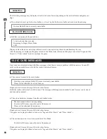
Page 74: ...ESSAGES Startup power on test This product displays the following messages when it detects an error Read the error description and follow the steps indicated Refer to the LINDBERGH Service Manual for...

Page 75: ...rently unavailable Please call an attendant to restock licenses Displayed at all times at the top of the Advertise Screen Refill the reader writer stocker with licenses The message will disappear auto...

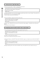
Page 76: ...damaged The data on this license is damaged Please call an attendant Displayed when data on the inserted Initial D License is damaged but may be restored A license inserted by hand is still in its ini...

Page 77: ...assistance 417 or 423 Displayed when a hardware problem occurs in the reader writer when reading or writing license data the game is halted The reader writer may be damaged Dispensing cards from the s...

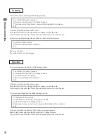
Page 78: ...or has occurred while writing license Please call an attendant 415 The game is halted Remove the license and reboot the cabinet The stocker dispenses a defective license faulty initialization etc Fail...

Page 79: ...physically stuck during ejection Your Initial D license is jammed Please press the Start and View Change buttons If you cannot eject your license please call an attendant for assistance 403 A license...

Page 80: ...UNTERMEASURES Send the LINDBERGH board in for repair with the key chip still in place Error 09 DISPLAY System Memory Not Enough CAUSE The LINDBERGH board does not have enough memory COUNTERMEASURES Se...

Page 81: ...hip is not connected COUNTERMEASURES Check that the key chip is connected correctly Check that the key chip is not inserted the wrong way or that the key chip from a different system is not inserted E...

Page 82: ...S Check that the DVD drive is connected correctly Check that the game disk is not scratched damaged or dirty Error 33 DISPLAY Storage Device is Not Acceptable CAUSE The program installer device cannot...

Page 83: ...has not been pulled out Error 43 DISPLAY IP Address Not Assigned CAUSE An IP Address could not be obtained from the DHCP server COUNTERMEASURES Check the network settings Set IP Address and other set...

Page 84: ...ck and malfunctioning Static electricity from your body may damage some electronics devices on the IC board Before handling the IC board touch a grounded metallic surface so that the static electricit...

Page 85: ...serted into it this board serves as a special purpose game board for the product Use with the dip switches DIP SW on the board at the prescribed settings If settings do not match the product an error...

Page 86: ...ER INPUT SW COVER TFF 1504 STEERING EMBLEM TFF 2002 B COCKPIT BASE L ID4 539 30 203 COCKPIT BASE R ID4 539 30 202 OTHER SIDE INSTRUCTION ID4 539 30 210 BILLBOARD PANEL TFF 0704 POP ID4 539 30 100 STIC...

Page 87: ...R TFF 1620 2 HEADREST BACK COVER TFF 1609 LOWER SEAT TFF 1605 UPPER SEAT ENG TFF 1603 01 CTRL PANEL COVER ENG TFF 1001 01 CTRL PANEL UPPER COVER BLANK TFF 1002 CTRL PANEL COVER L TFF 1003 STEERING WHE...

Page 88: ...IEW OF COIN DOOR MARQUEE SW VOL BD 838 14548 01 BACK OF MONITOR POWER SWITCH FAN 110V 99 60 900 Near by AC Power cord VGA CABLE STEERING MOTOR FL LAMP FOR MARQUEE 30W 18 MAIN POWER SW MAIN FUSE 10 AMP...

Page 89: ...2 838 14578 I O CONTROL BD 3 FOR JVS COM 838 14572 SERVO MOTOR DRIVE BD SER EMI 838 14592 01 JVS CABLE 515 60 682 RCA 515 60 680 TRANSFORMER 120V 100V 8 AMP 99 60 215 POWERSUPPLY DC24V LCA75S 24 400 5...

Page 90: ...231 B010 EDGING NEW TYPE L 10MM 201 000 F00408 0B M SCR FH BLK M4 8 202 000 P00508 WB M SCR PH W FS BLK M5 8 ASSY SPKR L TFF 0650 ITEM NO PART NO DESCRIPTION 1 TFF 0651 SPKR BRKT L 2 TFF 0652 SPEAKER...

Page 91: ...219 GEAR STAY 21 SPG 2220 WSHR 22 SPG 2221 NEUTRAL STOPPER D 23 TFF 2225 NEUTRAL SPACER B 101 100 5263 BEARING 12 OILES 80F 1212 102 220 5484 VOL CONT B 5K OHM 102 220 5753 VOL CONT B 5K OHM TOCOS 104...

Page 92: ...NPUT SW COVER 2 TFF 1502 INPUT SW RUBBER CONTACT 3 TFF 1503 INPUT SW BASE 4 TFF 1504 STICKER INPUT SW COVER 101 280 5277 CORD CLAMP 18 102 838 14707 RUBBER SW BD TFF 201 FAS 000097 M SCR PH W SMALL FS...

Page 93: ...F 2515 SPACER COLLAR C 101 350 5805 01 SERVO MOTOR Y21C 5010S 102 220 5484 VOL CONT B 5K OHM 102 220 5753 VOL CONT B 5K OHM TOCOS 103 310 5029 F20 SUMITUBE F F 20MM 104 601 11089 TIMING BELT 150 S5M 5...

Page 94: ...2410 CENTERING SPRING 11 TFF 2411 KNOCK BASE 12 TFF 2412 STOPPER SHAFT 13 TFF 2413 DESIGN PLT SHIFT UP 14 TFF 2414 DESIGN PLT SHIFT DOWN 15 TFF 2415 SPACER 101 370 5297 PHOTO INTERRUPTER GP1A75EJ000F...

Page 95: ...ample 51 WHITE RED Note 2 The character following the wire color code indicates the size of the wire U AWG16 K AWG18 L AWG20 None AWG22 The color codes for the wires used in the diagrams in the follow...

Page 96: ...7CH AGND AGND AGND NOT USED NOT USED A D 4CH AVCC A D 8CH AGND AGND UP STRAT SH I FT3 LEFT SH I FT2 SH I FT0 UP ROGHT GND GND GND CO I N 1 SH I FT1 DOWN DOWN V I EW 0 CHANGE V I EW 2 V I EW 1 V I EW 3...

Page 97: ...ANALOG I N 1 2 C 1 3 2 1 3 2 WH YL WH YL 1 2 F TFF 0650 ASSY SPKR L TFF 0660 ASSY SPKR R OL OL DL DL 1 2 A GO TO MAIN EARTH P 1 2 3 4 5 6 7 8 C WH YL 9 OPTION MARS DBA AE2451 U3E 99 70 178 or AE2451 U...

Page 98: ...PART 539 30 300 1st PRINTING SEPTEMBER 2007 SEGA AMUSEMENTS U S A INC 800 ARTHUR AVENUE ELK GROVE VILLAGE IL 60007 5215 PHONE 888 877 2669 FAX 847 427 1065 WEB WWW SAU SEGA COM...

Reviews: