background image

    BREEZAIR EXQ/EZQ/EXS EVAPORATIVE COOLERS INSTALLATION MANUAL  

|  

15


ILL1664-A

EXTRA NOTES FOR EZQ MODEL ONLY

2

3

1

ILL1645-A

ILL1894-A

PAD FRAME POSITIONS

When re-fitting pads, ensure that they are fitted in their 

original positions. 

EXQ210, EZQ215 and all EXS model 

coolers have pads that vary from the standard 90mm thickness. 

While removing the pad frames, take note of the location each 
belongs to.

Check for stickers indicating correct locations for thick or 
cut edge pads.

About Appliance

Displays information such as model number, serial number and 
software version for all coolers connected to the controller.

Min/Max Set Temperature

Defines the maximum and minimum temperature values.

Night Quiet Mode

Restricts fan speed to a specified level during a specified period.

Humidity Control (when Internal Air sensor is connected)

Set desired humidity levels.

External Air Sensor

See Pg 13 for details

Manual Drain

Turns cooler off and drains the tank.

Pad Flush

Turns cooler off and runs pump for a specified amount of time.

Drain And Dry

Cooler will drain and fan will run for 1 hour every day at a 

specified time.

Water Manager

Select the preferred water management method:

• 

Salinity Measurement - replaces water when Salinity level 

reaches set point.

• 

Timed Drain - drains Tank After 8 tank fill cycles or every 1-2 

hours (system dependant).

• 

No Drain Control - salinity control external to electronics 


eg. continuous bleed.

• 

No Water Thermostatic - allows Thermostatic control in VENT 

mode. No water present. Cooling performance is limited.

Weatherseal Open Speed

The cooler fan will turn on at the specified Weatherseal opening 

speed for the first 10 seconds each time it starts up. It will then 

return to the set fan speed.

Prewet

When COOL mode is activated, the pump will run for 90 

seconds before the fan is switched on.

Salinity Level

Sets the salinity level at which the tank will drain in “SALINITY 

MEASUREMENT” mode.

Tank Drain Delay

Sets the time delay before the drain valve opens after the pump 

in the cooler is turned off.

AutoClean

Select the preferred cleaning interval (50 / 100 / 200 hours). At 

8.00am after the selected running hours has been reached, the 

cooler will drain the tank, fill with fresh water and operate the 

pump for 5 minutes. When complete, drains the tank and returns 
to previous operation mode. 

Stickers adhered to the fan scroll indicate the correct position.

If fitted incorrectly they may cause problems:

•  Thicker pads may catch on internal components causing 

damage.

• 

Thicker pads may impede the correct operation of the float 

valve.

•  Incorrect positioning of pads may cause a drop in cooler 

performance.

• 

Incorrect fitment may allow water to bypass the pad and be 

carried over into the air stream and ducting. 

•  Water bypass may cause damage to internal electronic 

components.

TESTING THE PUMP

Test the pump by turning the cooler on at the MagIQtouch 

controller, in “COOL” mode. Check that water is evenly 

distributed to all pads. 

Note!

 If the cooler has not been on before it will run a “Pre-Wet” 

routine where the pump will operate to saturate the pads.  
This cycle takes 2 minutes, then the fan will start automatically.

ADJUSTING COOLER SETTINGS

Within the SETTINGS menu of the MagIQtouch Controller is the 

COOLER sub-heading. Here various settings of the cooler can 

be adjusted.

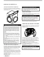
Before fitting the 4 main pad frames, make sure the 3 lower 

pads are refitted into their respective positions in the base 

of the cooler.

To refit the pad frame, locate the bottom edge in the tank 

groove, then push the top in under the lid. The frame 

should clip into the cooler with a firm push of the hand at 

the two points where the screwdriver was used. Remember 

to insert the corner clips after replacing the pad frame(s).

Summary of Contents for EXQ

Page 1: ... English INSTALLATION MANUAL EXQ EZQ EXS Evaporative Coolers ILL1672 A Original English Instructions ...

Page 2: ...NG THE DRAIN VALVE OR BLEED TRAY 11 HARMONY AND HORIZON DRAIN VALVE ASSEMBLY 11 HOMEMAKER BLEED TRAY 11 CONNECTING THE MAGIQTOUCH MAGIQCOOL CONTROLLER 12 COMMISSIONING THE COOLER 12 Diagnostic LED 12 Salinity LED 12 MagIQtouch Controller Information 13 External Air Sensor Feature 13 TESTING THE DIRECT DRIVE MOTOR 13 CHANGING THE WATER MANAGEMENT METHOD FOR THE MAGIQCOOL CONTROL 13 SETTING THE WATE...

Page 3: ... If a worker is alone who knows they are there and if they get into difficulty how can they summon help Call someone on the ground Mobile phone etc What condition is the roof in Should the trusses underside or surface be checked Does the worker have appropriate foot wear Flat sole jogger type is advisable Are all power cables extension leads safe and appropriately rated Are all ladders tools and e...

Page 4: ...tronics Test the Direct Drive motor STEP 21 CLEAN UP Clean up the site STEP 3 PREPARE DROPPER Cut hole fit grommet in dropper for cables STEP 8 CONTROLLER CABLE Connect one end of the controller cable to cooler electronics then feed the other into dropper Page 1 Page 7 Page 12 Page 16 Page 4 Page 12 Page 16 Page 8 Page 5 STEP 7 POWER CABLE Unhook the plug under the cooler Feed power cable down int...

Page 5: ...r STEP 10 REGULATIONS Read adhere to the local national electrical and plumbing regulations STEP 17 REFIT PAD FRAMES Refit the pad frames before testing the pump STEP 5 CONVEY COOLER Convey the cooler to the roof Note Always use 2 people when handling manually STEP 11 INLET SOLENOID Fit the solenoid Connect the cable Connect the water supply Install the drain pipe STEP 18 TEST PUMP Turn on the coo...

Page 6: ... flue 5m 17 from a sewer vent and 600mm 2 from a wall The cooler must be mounted at least 3m 10 preferably 5m 17 away from any TV antenna or antenna cables Make sure the cooler is not between the antenna and the transmission tower that is providing the television signal to the home Allow adequate access to and around the cooler for maintenance Provision must be made for access to electricity water...

Page 7: ...atherseal Before transporting to the roof temporarily screw the transition to the dropper using a screw in each corner Affix gauge timbers under the top and bottom edges of the transition with 30mm 1 2 screws supplied ILL1646 A ILL951 B EXTRA NOTES FOR EZQ MODEL ONLY MOUNTING THE DROPPER EXQ EXS MODEL EZQ MODEL ILL1647 A ILL182 H Install the dropper and securely fix it to the roof structure on 3 s...

Page 8: ...ion Pivot the transition dropper off the appropriate gauge timber top or bottom until the level reads true Hold dropper in place using one single screw into the rafter This will set the dropper at an angle of 24 Check for lateral level by placing level vials in the top or bottom wells Note Very few roof slopes will contact both gauge timbers once the dropper is properly levelled As a general rule ...

Page 9: ...the low gutter side of the installation EXTRA NOTES FOR EZQ MODEL ONLY ILL1292 B Important Ensure the four tab screws which are removed to separate the transition from the cooler are re fitted behind the tabs after the cooler has been fitted into position Carefully lift the cooler onto the transition piece and lower downwards ensuring all nine clips have engaged ILL1649 A ILL1650 A ILL525 D Check ...

Page 10: ... dropper grommet before fitting ductwork Note The maximum length for the wall control cable to travel alongside the power cable is 10m 33 WARNING Do not let the cable the cable ends or the control box get wet Position the cable in the dropper so they will be accessible from inside the roof space INSTALLING THE MAINS POWER CABLE The power cable included with your cooler will either have a mains soc...

Page 11: ...ed directly onto the manual water shut off valve Always ensure that the water pipe connection does not place sideways strain onto the float valve Homemaker A permanent water supply is required to be connected to the float valve The water connection point is located on the underside of the cooler The water connection fitting is a 1 2 BSP male adaptor suitable for a compression fitting Do not fit th...

Page 12: ... been fitted place the cover over the assembly Make sure the solenoid valve cable is retained in the groove in the cooler tank Secure the cover by tightening the flexible hose assembly nut C Important Make sure the cable cannot lay in the water at any stage Connect the electrical leads to the solenoid The electrical cable leads may be connected to the solenoid either way around Important If freezi...

Page 13: ... drain adaptor Make sure the drain water discharge flows freely away from the cooler Important Do not over tighten plastic fittings Connect the drain valve cable to the cooler electronics box HARMONY AND HORIZON DRAIN VALVE ASSEMBLY Assemble the drain valve as shown HOMEMAKER BLEED TRAY Fit the bleed tray as shown Screw the nut up tightly by hand underneath the cooler Do not overtighten Note Make ...

Page 14: ...lets in the following lengths Part No Length Details 833880 20m MagIQtouch Controller Cable No Ferrite 823553 20m MagIQtouch Controller Cable With Ferrite 862873 1 5m MagIQtouch Controller Cable No Ferrite 861265 3m MagIQtouch Controller Cable No Ferrite 864396 30m MagIQtouch Controller Cable With Ferrite 864402 40m MagIQtouch Controller Cable With Ferrite CONNECTING THE MAGIQTOUCH MAGIQCOOL CONTR...

Page 15: ...linity control to regular operation of the drain valve every 65 mins follow these programming steps To enter Parameter mode the following process must be carried out within 4 minutes of power being applied to the cooler If unsure of time since the last power ON remove power to the cooler Isolator Switch or Circuit Breaker for a minimum of 6 seconds so the mode can be entered 1 While wall control i...

Page 16: ...ir to fill with water The float valve will eventually stop the water from entering the cooler Wait for this to happen and check the water level If the level is too high rotate the float clockwise Drain some water from the tank and allow it to refill to the new set point If too low rotate the float in an anti clockwise direction For EXQ EXS model the correct water level is approximately 5mm above t...

Page 17: ...ump will run for 90 seconds before the fan is switched on Salinity Level Sets the salinity level at which the tank will drain in SALINITY MEASUREMENT mode Tank Drain Delay Sets the time delay before the drain valve opens after the pump in the cooler is turned off AutoClean Select the preferred cleaning interval 50 100 200 hours At 8 00am after the selected running hours has been reached the cooler...

Page 18: ...ing mode ensure all pads have even water saturation and there are no visible water leaks COOLER SECURE The cooler is secure and level on the dropper using all fixings supplied SEALED The dropper and all penetrations are correctly flashed and sealed WEATHERSEAL OPERATES The Weatherseal operates correctly and can open and close without interference PLUMBING FLUSHED The water pipes were flushed of an...

Page 19: ...estart the cooler MagIQtouch Controller failure Replace MagIQtouch Controller Pump runs but no water circulation Pump runs but pads lack water Insufficient water in tank Adjust float level Water hoses blocked Check and clean out blockage Pump strainer blocked Clean pump strainer Insufficient water supply pressure Check and confirm water supply pressure Water solenoid is installed incorrectly Check...

Page 20: ...NGHAM NG15 7HP UNITED KINGDOM SEELEY INTERNATIONAL AMERICAS LTD 1002 S 56TH AVENUE SUITE 101 PHOENIX ARIZONA 85043 USA SEELEY INTERNATIONAL AFRICA PTY LTD 6 WITTON ROAD FOUNDERSVIEW SOUTH MODDERFONTEIN 1609 GAUTENG SOUTH AFRICA EXQ EXS Cooler Installation Manuals Now provided on the internet available in English French German Italian and Spanish Refer www seeleyeurope com French Manuel d Installat...

Reviews: