


BREEZAIR EXQ/EZQ/EXS EVAPORATIVE COOLERS INSTALLATION MANUAL
|
13
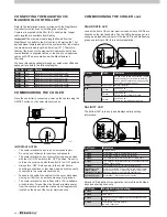
LED
Indicates
Hall Effect
ON = Normal operation.
OFF = One or more Hall effects sensors in motor not detected.
Thermal O/L
ON = Normal Operation.
OFF = Thermal Overload in motor tripped.
(
Caution!
Motor in overload may re-start without warning).
Fan Speed
ON = Normal Operation.
OFF or Flashing = Motor is not rotating within 30% of its set
speed.
Power
Mains power is applied to the motor when the fan ON button of
the controller has been pressed.
ILL1651-A
ILL1641-A
ILL1823-A
COMMISSIONING THE COOLER cont.
MAGIQTOUCH CONTROLLER INFORMATION
Diagnosis and cooler operating information can also be viewed
from the MagIQtouch Controller. Faults are displayed on the
screen as they occur.
Current cooler operation information can be temporarily
displayed on the “Status Information Display” option in the
GENERAL SETTINGS menu.
When this option is turned on, a temporary information display
window becomes accessible on all MANUAL and PROGRAM
screens.
TESTING THE DIRECT DRIVE MOTOR
This Breezair cooler incorporates a Seeley electronically
commutated Direct Drive motor. No setup is required for this
motor as it automatically adjusts to provide optimum output for
each installation.
Turn the cooler on at the MagIQtouch Controller, in “FAN ONLY”
mode. Look at the front of the cooler electronics box where 4
LEDs are situated on the left hand side. LEDs 1 - 4 should be
on (glowing green).
CHANGING THE WATER MANAGEMENT
METHOD FOR THE MAGIQCOOL CONTROL
For models where WaterMiser probes and drain valve are fitted,
the drain frequency is typically managed by salinity control. If
you do wish to change from salinity control to regular operation
of the drain valve every 65 mins, follow these programming
steps.
To enter Parameter mode, the following process must be
carried out within 4 minutes of power being applied to the
cooler. If unsure of time since the last power “ON”, remove
power to the cooler (Isolator Switch or Circuit Breaker) for a
minimum of 6 seconds so the mode can be entered.
1. While wall control is OFF, push and hold
and
buttons for minimum three (3) seconds. The screen will then
display “A1” - (Water Salinity Control Method) and “Param”.
2. Press
to enter the “value” screen.
3.
To alter the “value” of selected parameter, press
or
. Numbers will change to show different values the
parameter can be set to.
WaterMiser = 0
Timed Drain = 1 (every 65 mins)
Non-Drain Valve salinity control (bleed etc.) = 2
4. To store the value, press
. Screen will go blank
momentarily as wall control stores parameter change, and
returns screen to “Param” screen.
5. To exit parameter mode or escape from an alteration without
storing a change press
button instead of
button.
Note!
Once step 4 has been carried out, new parameter
change is permanent until again altered.
6. If no buttons are pushed on wall control, after 3 minutes
screen will reset to “OFF” state. Procedure to enter parameter
mode must be re-initiated.
EXTERNAL AIR SENSOR FEATURE
EXS models are fitted with an External Air Sensor. This feature
has 3 functions.
1. Display ambient external temperature.
2. Turns the pump off at a desired external ambient temperature
set point. Internal thermostat temperature set point or fan speed
will be maintained as configured.
3. Automatically drain the tank based on external temperature
conditions. In certain geographic locations this will prevent the
water from freezing inside the tank.
To switch this feature on go to SETTINGS within the COOLER
tab and select EXTERNAL AIR SENSOR.
ILL2152-A


