184
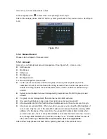
Here is for you to view and implement hard disk management. See Figure 5-45.
You can see current HDD type, status, capacity and record time. When HDD is working properly,
system is shown as O. When HDD error occurred, system is shown as X.
z
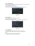
Alarm set: Click alarm set button, the interface is shown as below. See Figure 5-46. (This
interface is just like the abnormity setup). Please refer to chapter 5.5.2 for detailed
information.
z
HDD operation: You can select HDD mode from the dropdown list such as read-only or you
can erase all data in the HDD. Please note system needs to reboot to get all the modification
activated.
Figure 5-45
Please highlight icon
to select the corresponding function.
Figure 5-46
For the HDD group setup operation, please note:
z
Each channel’s records can be stored into the specified HDD Group.
z
Each HDD Group is corresponding to several hard disks, while one hard disk is only
included in one HDD Group.
Summary of Contents for DVR-HD016240M
Page 97: ...86 Figure 2 30 2 3 4 HD SDI 1080P 1U Series The connection sample is shown as in Figure 2 31...
Page 99: ...88 Figure 2 32 2 3 6 General 1 5U series Please refer to Figure 2 33 for connection sample...
Page 130: ...119 HD SDI 1 5U Mini 2U Series Figure 3 18...
Page 152: ...141 Figure 4 27 Figure 4 28 Figure 4 29...
Page 157: ...146 Figure 4 34 Figure 4 35 Figure 4 36...
Page 165: ...154 Figure 4 52...
Page 169: ...158 Figure 5 3 Figure 5 4 Figure 5 5 Figure 5 6...
Page 177: ...166 Figure 5 16 Figure 5 17 Figure 5 18 5 3 5 3 NTP Setup...
Page 218: ...207 Figure 6 11...
Page 288: ...277 Maxtor DiamondMax 20 STM3250820AS 250G SATA...


