background image

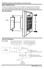
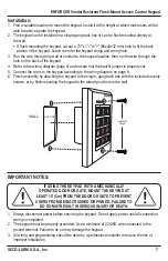
CUTOUT

WALL

Installation

screws

7

ENFORCER Vandal Resistant Flush-Mount Access Control Keypad

SECO-LARM U.S.A., Inc.

Installation:

IMPORTANT NOTES:

1.  Find a suitable location to mount the keypad. Install it at the height at which most users will be 

able to easily operate the keypad.

2. 

The keypad can be installed in a single-gang back box or can be flush-mounted directly to 


the wall.


If flush-mounting the keypad, cut out a 2

5

/

8

”x1

3

/

4

”x1

1

/

4

” (66x44x32 mm) hole to fit the back 

portion of the keypad. Leave room for the keypad wiring and wiring hole.

3.  Run the wire through the wall or conduit to the keypad location, then run the wire through the 

hole on the back of the keypad.

4. 

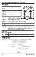
Refer to the wiring diagram (page 8) and ensure that the backlit jumper is properly set.

5.  Connect the wires to the keypad according to the wiring diagram on page 8.

6. 

Finish assembly by attaching the keypad to the single- gang back box with the included security 

screws, or by flush-mounting the keypad in the already-cut hole in the wall.

1. 

Always disconnect power before servicing the keypad. Do not apply power until all connection 

wiring is completed.

2. 

The keypad must be properly grounded. Use a minimum of 22AWG wire connected to the 

ground terminal. Failure to do so may damage the keypad.

3.  All wiring and programming should be done by a professional installer to reduce the risk of 

improper installation.

IF USING THE KEYPAD  WITH A MECHANICALLY 

OPERATED DOOR OR GATE, MOUNT THE KEYPAD AT 

LEAST 15’ (5m) FROM THE DOOR OR GATE TO PREVENT 

USERS FROM BEING CRUSHED OR PINNED. FAILURE TO 

DO SO MAY RESULT IN SERIOUS INJURY OR DEATH.

Summary of Contents for Enforcer SK-1123-FDQ

Page 1: ...SK 1123 FDQ Vandal Resistant Flush Mount Access Control Keypad Manual...

Page 2: ...ypad SECO LARM U S A Inc Quick Installation Guide Mounting Diagram Quick Wiring Diagram This page is for installers looking to do a basic installation and programming of the keypad For more in depth i...

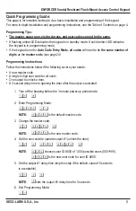
Page 3: ...ter code see page 24 Programming Instructions Follow the instructions below if the following covers your needs A new master code A single 4 digit user code for all users One output to unlock a door A...

Page 4: ...gramming the Master Code 13 Programming the Super User Code 14 15 Programming User Codes 16 Programming Visitor Codes for Output 1 17 Programming Duress Codes 18 19 Programming the Output Mode and Out...

Page 5: ...s which can be programmed for one time or limited time use 1 99 hours Output 1 Form C relay 1A 30VDC max Output 2 Transistor ground 100mA 24VDC Outputs 1 and 2 can be programmed to activate for up to...

Page 6: ...n standby mode 3 1 Flash sec System restore mode 2 Beeps Fast flashing for 2 5 min Code already stored 1 Long beep Real time clock stopped after power loss Continuous 3 fast beeps every 5 seconds NOTE...

Page 7: ...m page 8 and ensure that the backlit jumper is properly set 5 Connect the wires to the keypad according to the wiring diagram on page 8 6 Finish assembly by attaching the keypad to the single gang bac...

Page 8: ...utput max 100mA 24VDC Triggers a silent alarm or other device when the user enters a duress code Egress Input N O Pushbutton contact to ground Press button to activate Output 1 Ground Common ground ou...

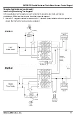
Page 9: ...Lock System Using Two Keypads In this application two keypads are each connected to separate door locks and egress pushbuttons While one door is open the other cannot be opened Use an N C magnetic con...

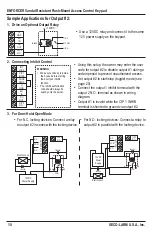
Page 10: ...e inhibit authorization code should always be kept by only the owner 12VDC Power Supply Electric Lock N O N C OUTPUT 1 COM COM N O O P 2 N O Electric Lock IN4004 IN4004 N C N O 12VDC Power Supply N C...

Page 11: ...bout 1 minute During this power up time if needed use Direct Access to Programming DAP to reset the master code see Direct Access to Programming DAP on page 28 1 Turn off the beeping before the 1 minu...

Page 12: ...17 41 Duress codes for output 1 No default must be programmed 18 19 42 Duress codes for output 2 No default must be programmed 18 19 51 Output mode for output 1 5 Second output momentary 20 52 Output...

Page 13: ...ult values and are ready to be re programmed At this point the keypad is still in programming mode Programming the Master Code The master code is used to enter programming mode The master code does no...

Page 14: ...nd Exit Programming Mode on page 11 2 Enter the new super user code 02 xxxx NOTE XXXX represents the new super user code which can be 4 to 8 digits long There can be only one super user code for the k...

Page 15: ...isable period 2580 8 NOTE This function is used to enable the operation of output 1 if it was disabled using the auto disable function see pages 22 23 When the output 1 auto disable function is inacti...

Page 16: ...programmed user codes for the selected output User IDs 000 to 999 1 000 unique user IDs for user codes for output 1 001 to 100 100 unique user IDs for user codes for output 2 User Codes A user code ca...

Page 17: ...Visitor IDs 01 to 50 50 unique visitor IDs for visitor codes for output 1 0999 Delete all currently programmed visitor codes Valid Duration 00 Set a one time code This code can only be used once by a...

Page 18: ...be the same as a user s normal user code but with a single digit changed as by subtracting or adding 1 to the first or last digit of the code For example if the user code is 1369 a good duress code m...

Page 19: ...ser code both the appropriate outputs 1 or 2 and the duress output will be activated However a duress code cannot deactivate the duress output Only a normal user code super user code or a master code...

Page 20: ...general formula AA BBBBB A Output B Output Mode and Time Outputs 51 Output 1 52 Output 2 Output Mode and Time 0 Start stop toggle mode In this case the output starts when a user code is entered and st...

Page 21: ...rs and Minutes HH represents hours and MM represents minutes in the military 24 hour time format from 00 00 to 23 59 Examples 1 Set the real time clock to 11 30 AM 55 1130 2 Set the real time clock to...

Page 22: ...cannot be the same The output 1 auto disable time can be temporarily paused and restarted using the super user code see Programming the Super User Code on pages 14 15 During the output 1 auto disable...

Page 23: ...60 Program Wrong Code System Lock Up AA Lock Options Lock Options Choose from several different options for the wrong code system lock up security level 1 After 10 successive false attempts using inc...

Page 24: ...ion Sounds on page 25 Programming the User Code Entry Mode The keypad can be programmed for auto or manual user code entry modes Auto entry mode Pressing the key is not required after typing in a user...

Page 25: ...e keypad will not beep if the door is opened with a user code or the egress button Programming the Amber LED Flashing during Standby Mode The keypad s amber LED typically flashes while the keypad is i...

Page 26: ...ns for the SK 1123 FDQ 1 Momentary contact with no warning default Press the egress button momentarily The door opens instantly default or after the programmed relay time with no audible warning 2 Mom...

Page 27: ...y users of the delay time Delay Time 0 No delay time default Output 1 operates immediately when the egress button is pressed 1 to 99 Egress button delay time The delay time can be set from 1 to 99 sec...

Page 28: ...e of continual development and improvement For that reason SECO LARM reserves the right to change specifications without notice SECO LARM is not responsible for misprints Trademarks are the property o...

Reviews: