


O/P 2
N.O.
DU
OUT
EG
IN
(-)
GND
N.C.
+12VDC
O/P 2
N.O.
DU
OUT
EG
IN
(-)
GND
O/P 2
N.O.
N.C.
N.C.
N.C.
OUTPUT
#1
COM
COM
COM
N.O.
N.C. OUTPUT
#1
COM
N.O.
O/P 2
N.O.
O/P 2
N.O.
DU
OUT
EG
IN
(-)
GND
O/P 2
N.O.
DU
OUT
EG
IN
(-)
GND
DOOR
SENS
O/P 1
INHIB
INT.
LOCK
N.C.
or
N.O.
TO ALARM
CONTROL PANEL
PROTECTION ZONE
Terminals in Alarm
Control Panel for
connecting Remote
Arm/Disarm control
switch
NO or NC Contact
ALARM CONTROL PANEL
IN4004
N.C.
COM
N.O.
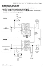
WARNING
•
Make sure nobody is inside
the house before starting
the door lock inhibit
function.
•
The inhibit authorization
code should always be
kept by only the owner.
12VDC
Power
Supply
12VDC
Power
Supply
+
+
+
+
-
-
-
-
Electric Lock
Electric Lock
N.O.
N.O.
O/P 2
N.O.
DU
OUT
EG
IN
(-)
GND
N.C.
+12VDC
O/P 2
N.O.
DU
OUT
EG
IN
(-)
GND
O/P 2
N.O.
N.C.
N.C.
N.C.
OUTPUT
#1
COM
COM
COM
N.O.
N.C. OUTPUT
#1
COM
N.O.
O/P 2
N.O.
O/P 2
N.O.
DU
OUT
EG
IN
(-)
GND
O/P 2
N.O.
DU
OUT
EG
IN
(-)
GND
DOOR
SENS
O/P 1
INHIB
INT.
LOCK
N.C.
or
N.O.
TO ALARM
CONTROL PANEL
PROTECTION ZONE
Terminals in Alarm
Control Panel for
connecting Remote
Arm/Disarm control
switch
NO or NC Contact
ALARM CONTROL PANEL
IN4004
N.C.
COM
N.O.
WARNING
•
Make sure nobody is inside
the house before starting
the door lock inhibit
function.
•
The inhibit authorization
code should always be
kept by only the owner.
12VDC
Power
Supply
12VDC
Power
Supply
+
+
+
+
-
-
-
-
Electric Lock
Electric Lock
N.O.
N.O.
N.C. OUTPUT
#1
COM
COM
N.O.
O/P 2
N.O.
+
-
+
-
Electric Lock
IN4004
IN4004
N.C.
N.O.
12VDC
Power Supply
N.C.
COM
N.C. OUTPUT
#1
COM
N.O.
O/P 2
N.O.
+
-
+
-
Electric Lock
N.O.
IN4004
IN4004
12VDC
Power
Supply
10
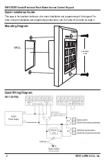
ENFORCER Vandal Resistant Flush-Mount Access Control Keypad
SECO-LARM U.S.A., Inc.
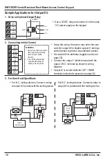
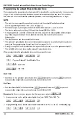
1. Drive an Optional Output Relay
2. Connecting Inhibit Control
•
Use a 12VDC relay and connect it to the same
12V power supply as the keypad.
•
Using this setup, the owner may enter the user
code for output #2 to disable output #1 during a
certain period to prevent unauthorized access.
•
Set output #2 to start/stop (toggle) mode (see
page 20).
•
Connect the output 1 inhibit terminal with the
output 2 N.O. terminal as shown in wiring
diagram.
•
Output #1 is invalid while the O/P 1 INHIB
terminal is shunted to ground via output #2.
3. For Door-Hold-Open Mode
•
For N.C. locking devices: Connect a relay
to output #2 in series with the locking device.
•
For N.O. locking devices: Connect a relay to
output #2 in parallel with the locking device.
Sample Applications for Output #2: