background image

Page 29

VS8197.V2    Issue: 1 - 23/11/11

Original Language Version

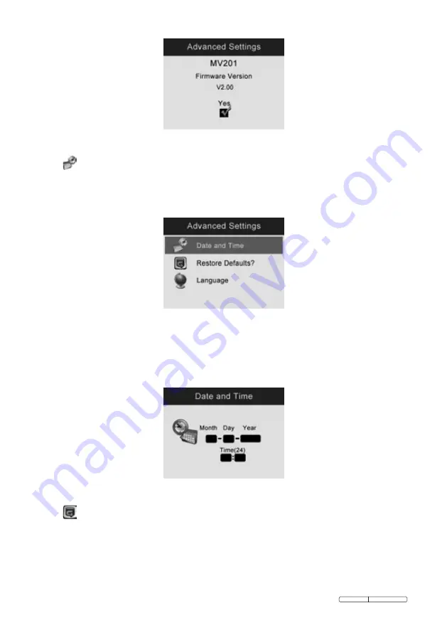
Fig. 33

15)


 – Sets date and time.

When you enter 

• 

Advanced Settings

, select 

Date and Time

 and press 

OK 

button.

Fig. 4

Use 

• 

UP

 and 

DOWN

 arrow buttons to set exact date and time, while using 

LEFT

 and 

RIGHT

 arrow buttons to move from one item to another and 

press 

OK

 button to save.

Fig. 35

16)


 – Asks if restore factory defaults.

Select 

• 

Restore Defaults

 from 

Advanced Settings

 and press 

OK 

button.

Summary of Contents for Auto Service VS8197.V2

Page 1: ...cifications 12 4 3 Charger Inspection 12 4 4 Battery Charging Procedures 13 5 Operation Instructions 14 5 1 Basic Operation 14 5 2 Operation Precautions 15 5 3 Tool Inspection 16 5 4 Tool and Work Area Set Up 17 5 5 On Screen Navigation 18 5 6 Icons 24 5 7 Software Update 31 6 Troubleshooting 32 InStructIonS for video bore scope Model no vs8197 v2 thank you for purchasing a Sealey Heater Manufactu...

Page 2: ...anders children and visitors away while operating the tool Keep the scope dry clean free from oil water and grease Use a mild detergent on a clean cloth to clean the outside of the scope when necessary 1 2 Electrical Safety For Use Of Charger uSe onlY tHe SuPPlIed cHArGer PluG for connectInG Bore ScoPe to tHe PoWer SuPPlY WArNiNG It is the user s responsibility to read understand and comply with t...

Page 3: ...wer any other electrical item DO NOT get the charger wet or use in wet damp conditions for indoor use only 1 3 Battery Safety Also see 4 1 Battery Charging Safety WARNING To reduce the risk of burns or fire DO NOT Attempt to open disassemble modify or service the battery pack DO NOT Crush puncture short external contacts or dispose of in fire or water DO NOT Expose to temperatures above 60 C 140 F...

Page 4: ...fety equipment is available from your Sealey dealer Account for all tools and parts being used and do not leave any in or near the engine Be alert to your surrounding environment while using the bore scope Note the location of the object to be inspected and determine a route to it Bend the bore scope shaft to follow the route 2 Description Specifications and Tool 92 1 Description Feature packed pr...

Page 5: ...n battery pack 3 7 Volt Estimated battery life 5 hours of continuous use Dimensions 255 x 108 x 36mm 10 x 4 25 x 1 42 Weight Net 0 6kg 1 3lbs Gross 2 6kg 5 7lbs Recording medium Internal memory or SD card SD card is optional and not included Image controls Zoom low light vision Lighting Fully adjustable LED Cable reach 1m 3 expandable to 8m 26 w optional extensions Imager head 5 5mm 0 22 waterproo...

Page 6: ... display unit Video output RCA 2 3 Accessories Included 1 Protective carrying case 2 USB cable 3 Video out cable 4 Charger 5 Magnet and mirror 6 Imager head and cable 5 5mm 7 User s Manual 2 4 Tool Components Note Because of continuing improvements actual product may differ slightly from pictures The VS8197 comes with the following items ...

Page 7: ... Connects to the tool while in use 3 Cable Connector Connects the display unit to the imager head and cable 4 Imager Head Connects to the cable to view real time images 5 Rubber Boot Protects the tool from drop abrasion etc Fig 2 6 Accessory Magnet Picks up small metal objects such as dropped rings or screws on the floor ...

Page 8: ... viewed screen C Camera Video Button Helps capturing a photo while pressing again will capture a video D Play Button Moves to play captured photos and videos E Bin Reverse Button Deletes captured photos and videos in the play mode Pressing again will control the direction of the real time image and video in the live screen The real time image and video will do a horizontal reverse or a vertical re...

Page 9: ...t Connects the tool to the mains with the supplied charger for battery charging K Video out Port Connects the tool to a TV with the supplied video out cable to view real time images L Earphone Port Inserts the optional earphone with microphone into the earphone port to help recording M Charging Indicator Light When the battery is charging the charging indicator light will be red When the battery i...

Page 10: ... 4 are properly aligned Once they are aligned tighten the knurled knob to hold the connection firmly in place Fig 4 3 2 Accessories Installation The two accessories include a magnet and a mirror Fig 2 Both of the accessories are attached to the imager head in the same manner here we are showing you how to attach the accessories using a magnet as an example Hold the imager head as shown in Fig 5 Fi...

Page 11: ...reen To remove an SD card gently push the SD card inward and then release to eject it from the card slot 3 4 USB Cable Connection Use the supplied USB cable to connect the tool to a PC to upload and view captured photos and videos A USB Connected message will appear on the screen 3 5 Video Out Cable Connection Insert the video out cable into the video out port of the tool and the other end of the ...

Page 12: ... NOT charge battery near fire or in sunlight Proper care will prevent serious damage to the charger 4 2 Battery and Charger Specifications Input 100 240 VAC 12 VDC 50 60Hz Output 5V DC Battery Type 3 7V lithium ion Battery Capacity 4200 mAh Input Current 0 3A 1A DC Charging Time 5 6 hours Cooling Passive convection cooling No fan 4 3 Charger Inspection CAUTION Before using inspect the charger for ...

Page 13: ...ool has a 3 7V built in lithium ion rechargeable battery When the battery is low a Battery critically low message appears and suggests you to charge the battery There are two means of charging battery 1 To charge battery by charger Locate the DC power port on the tool With dry hands connect the tool to the mains charger to start charging 2 To charge battery by USB cable Locate the USB port With dr...

Page 14: ...nd DOWN arrow buttons to zoom in or out while in the camera mode where you can see a zoom indicator bar as you adjust zoom 4 Press LEFT and RIGHT arrow buttons to increase or decrease LED brightness while in the camera mode where you can see a brightness indicator bar as you adjust LED light intensity 5 Press Play button to view captured photos and videos 6 Press Bin button to delete captured phot...

Page 15: ...soapy water to wash hands and other exposed skin after using the tool to inspect drains and other areas that may contain chemicals or bacteria When the inspection is completed carefully withdraw the imager head and cable from inspection area Store idle components out of the reach of children and other untrained persons Maintain the tool with care Properly maintained tools are less likely to cause ...

Page 16: ...ger head Let the water evaporate before using again Inspect the full length of the cable for cracks or damage Make sure the connections between the display unit and imager head and cable are tight All connections must be properly assembled for the cable to be waterproof NOTE Please check following methods to avoid injury FOR WALLS For inspecting the inside of walls be sure to close the electrical ...

Page 17: ... are present especially in the case of drains Chemicals may damage or degrade the tool Check the temperature of the area The working temperature of the tool is between 32 F 0 and 113 F 45 Check if any moving parts are present in the area Make sure the tool has been properly inspected 4 Install the correct accessories for use in the appropriate application 5 CAUTION Make sure the tool has been powe...

Page 18: ...what the imager head sees is displayed on the screen You can zoom adjust LED brightness rotate images and videos view and capture photos and videos from this screen 3 Switching from Still Image Capture to Video Capture The tool defaults to still image capture when powered on Press Video Camera button to switch between still image capture and video capture as required 4 Adjusting LED Brightness Pre...

Page 19: ... mode to zoom in or out A zoom indicator bar will be displayed on the screen as you adjust zoom Fig 8 Fig 8B 6 Entering the Primary Settings Screen Pressing the Setting button while in the live screen will take you to the primary settings screen Fig 9 Pressing Back button at any point will take you back to the live screen Fig 9 ...

Page 20: ...con is present at the top left portion of the screen Fig 11 Press OK button to start capturing video You will notice that a Rec icon appears at the top right portion of the screen just below battery capacity icon This shows that video is capturing The time at the top left portion just below video icon will begin counting down This indicates how much video you can store in the internal memory or SD...

Page 21: ... Fig 12 and Fig 13 Fig 12 Fig 13 While in the photo mode press OK button and use LEFT and RIGHT arrow buttons to play back captured photos one after another use UP and DOWN arrow buttons to zoom in and out While in the video mode press OK button and use LEFT and RIGHT arrow buttons to play back captured videos one after another ...

Page 22: ...ing and then the icon will appear Then press OK button to play recording while pressing OK again will pause playing record mode Fig 16 and Fig 17 Fig 16 Fig 17 If you wish to delete the recording use LEFT and RIGHT arrow buttons to select icon Fig 18 Fig 18 While in the video mode select a video which has been recorded and press OK button to start playing recording while pressing OK again will pau...

Page 23: ...ton to delete captured photos and videos and a Are you sure you want to delete this file message appears on the screen Fig 19 and Fig 20 Use LEFT and RIGHT arrow buttons to select Yes or No then press OK button to save your selection Fig 19 Fig 20 When you delete all the photos and videos a No Files Available message appears on the screen ...

Page 24: ...y Capacity Fully charged battery 2 SD Card Indicates an SD card has been inserted into the tool 3 Still Camera Indicates the tool is operating in still camera mode 4 Video Camera Indicates the tool is operating in video camera mode 5 Indicates you to begin playing recording in the photo play mode 6 Indicates you to start recording in the photo record mode 7 Indicates you are recording in the photo...

Page 25: ...tup and press OK button to modify advanced settings Fig 23 When necessary use UP and DOWN arrow buttons to select Date and Time Restore Defaults and Language from Advanced Settings 12 2 Displays colour or black white Colour is the default mode Select Color or Black White from Setup and press OK button ...

Page 26: ... from Colour mode to Black White mode then press OK button to save your selection If you wish to view or capture colour images and videos select Colour from Setup Fig 25 If you wish to view or capture black white images and videos select Black White from Setup Fig 26 13 2 Asks if you would like to format media ...

Page 27: ...K button and then use LEFT and RIGHT arrow buttons to select Yes then press OK button to save your selection Fig 28 If you do not wish to format media use LEFT and RIGHT arrow buttons to select No to return to previous menu Fig 29 If you select Yes a message Warning this will erase ALL files in memory appears on the screen Press OK button to save your selection and return to previous menu ...

Page 28: ... Version VS8197 V2 Issue 1 23 11 11 Fig 30 If you do not wish to format media select No toreturntopreviousmenu Fig 31 14 2 Displays firmware version Select Help from Setup and press OK button to display Firmware Version Fig 32 ...

Page 29: ...ings select Date and Time and press OK button Fig 4 Use UP and DOWN arrow buttons to set exact date and time while using LEFT and RIGHT arrow buttons to move from one item to another and press OK button to save Fig 35 16 Asks if restore factory defaults Select Restore Defaults from Advanced Settings and press OK button ...

Page 30: ...f you wish to restore factory defaults use LEFT and RIGHT arrow buttons to select Yes or No then press OK button to save your selection Fig 37 If you do not wish to restore factory defaults select No to return to previous menu Fig 38 17 Displays multi language interface ...

Page 31: ...red language and press OK button to save your selection Fig 40 5 7 Software Update NOTE The tool supports software updates 1 Format your SD card to FAT file format on a computer 2 Visit our website www sealey co uk and download software update file to your SD card 3 Insert your SD card into the SD card slot See 3 3 SD Card Installation 4 Press UP arrow button and then press Power button to turn on...

Page 32: ...ey under the Warranty is limited to either the repair or at the option of Sealey replacement of the tool at no charge with Proof of Purchase The sales receipt may be used for this purpose 2 This warranty does not apply to damages caused by improper use accident flood lightning or if the product was altered or repaired by anyone other than the Manufacturer s Service Centre 3 Sealey shall not be lia...

Page 33: ...tools accessories and packaging should be sorted taken to a recycle centre and disposed of in a manner which is compatible with the environment When the product is no longer required it must be disposed of in an environmentally protective way contact your local solid waste authority for recycling information battery removal open the rear cover by removing the six cover screws using a Phillips head...

Page 34: ... 14 EC Outdoor Noise Emissions Directive 2006 95 EC Low Voltage Directive 2002 96 EC WEEE Directive 2004 108 EC EMC Directive 2002 95 EC RoHS Directive 93 68 EEC CE Marking Directive 97 23 EC Pressure Equipment Directive And the following harmonised standard s Technical file compiled by Jack Sealey Ltd Signed Date Place Bury St Edmunds Name Position Being the responsible person appointed by the ma...

Reviews: