Section 01
SERVICE TOOLS AND PRODUCTS
Subsection 02
(MANDATORY SERVICE TOOLS)
SMR2000-038_01_02A.FM
01-02-3
Engine leak tester kit
P/N 295 500 352
Pump only
P/N 529 021 800
F01B2Q5
APPLICATION
717 and 787 engines.
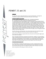
Supplementary engine leak test
kit
P/N 295 500 780
1) 787 RFI Intake plate
P/N 296 000 024
2) 947 Intake plate
P/N 296 000 025
3) 947 Rave plate
P/N 296 000 026
4) 947 Exhaust plate
P/N 296 000 027
APPLICATION
787 RFI and 947 engines.
NOTE:
This kit is supplementary
to P/N 295 500 352.
Intake plug
P/N 529 035 708
APPLICATION
947 DI engine.
Handle
P/N 420 877 650
A00C3V4
APPLICATION
Use with pushers (P/N 290 876
609 and 290 877 740).
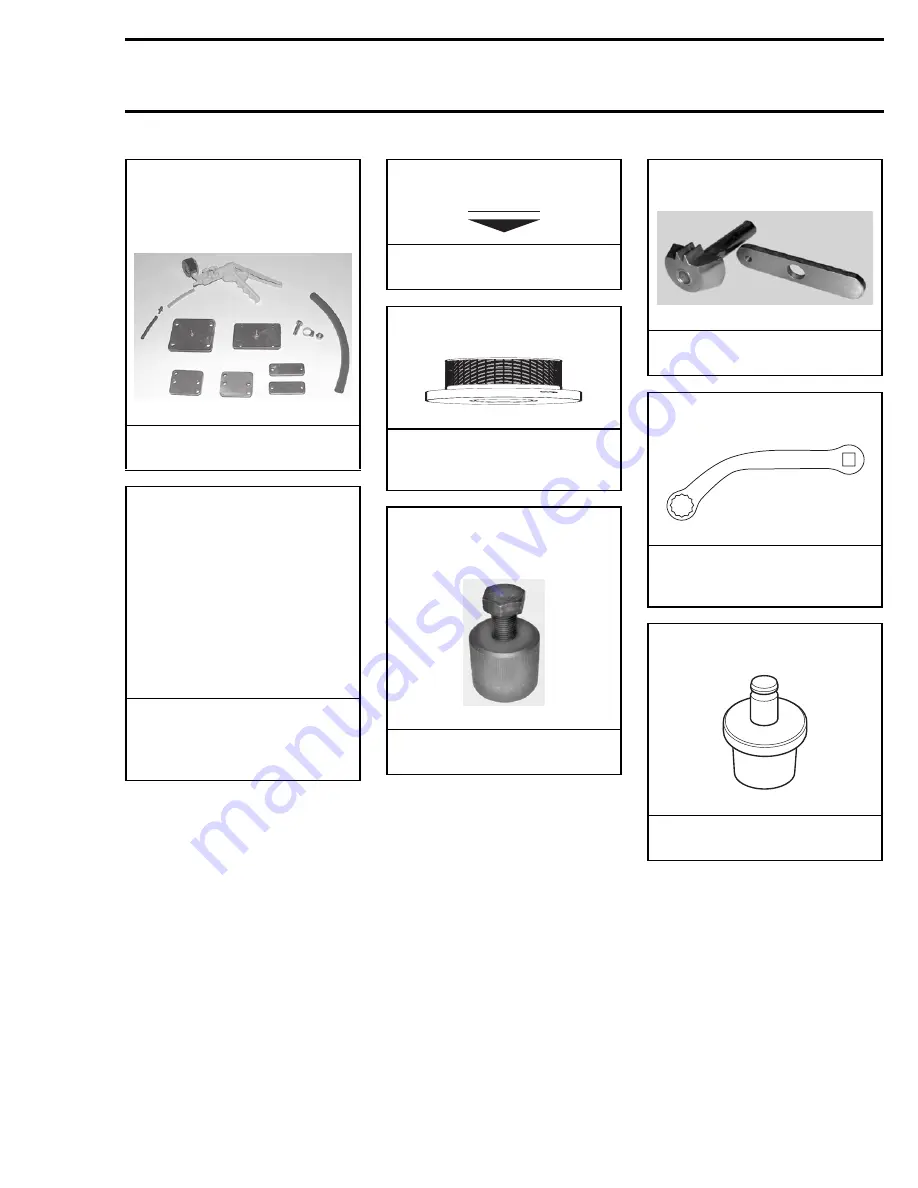
Ring gear puller tool
P/N 420 976 235 (puller ass’y)
P/N 529 035 549 (puller bolt)
F01B294
APPLICATION
787 and 947 engines.
NEW
Ring gear blocking tool
P/N 295 000 155
F01B264
APPLICATION
787 engine.
Polygonal wrench
P/N 529 035 505
F00B0Y4
APPLICATION
Exhaust system of the 947
engine.
Rotary valve shaft pusher
P/N 290 876 690
F01B2B4
APPLICATION
787 engine.
www.SeaDooManuals.net
Summary of Contents for 2001 RX
Page 1: ...www SeaDooManuals net ...
Page 2: ...2000 Shop Manual VOLUME 2 RX RX DI GTX DI www SeaDooManuals net ...
Page 345: ...SMR2000 073_14_00A FM RX MODEL 5513 5514 www SeaDooManuals net ...
Page 346: ...SMR2000 073_14_00A FM F16Z01 www SeaDooManuals net ...
Page 347: ...SMR2000 073_14_00A FM RX DI MODEL 5646 5656 www SeaDooManuals net ...
Page 348: ...SMR2000 073_14_00A FM F12Z02 www SeaDooManuals net ...
Page 349: ...SMR2000 073_14_00A FM GTX DI MODEL 5649 5659 www SeaDooManuals net ...
Page 350: ...SMR2000 073_14_00A FM F12Z01 www SeaDooManuals net ...
Page 351: ...www SeaDooManuals net ...