Section 04
COOLING SYSTEM
Sub-Section 02
(COMPONENTS)
04-02-7
4, Water Flow Regulator Valve
A water flow regulator valve has been developed
for the 787 engine so that it can produce the max-
imum horsepower output and yet maintain the
necessary diameter of the injection fitting at the
tuned pipe head for unobstructed water flow.
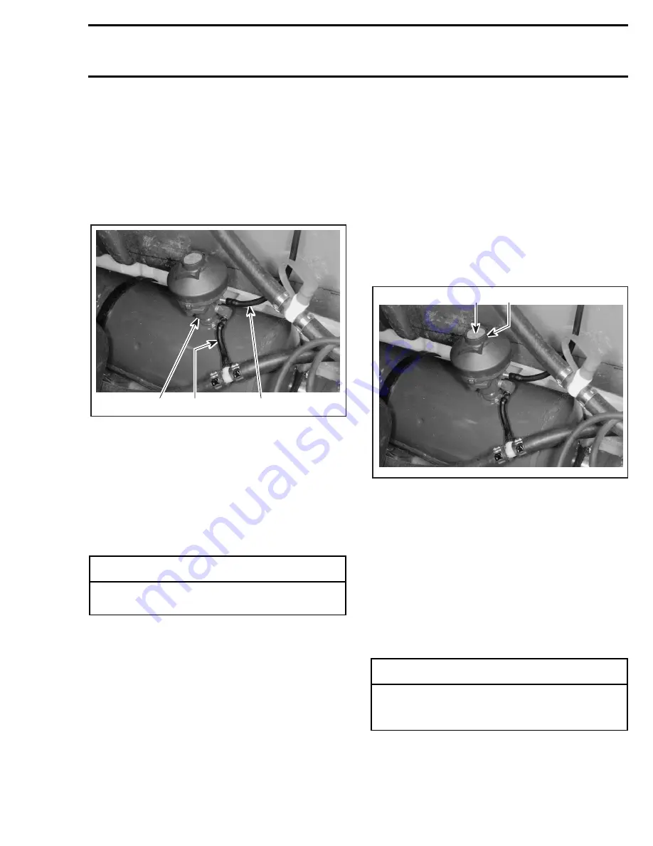
The water flow regulator valve is mounted directly
onto the muffler.
1. Water supply hose of regulator valve
2. Regulated water to injection fitting at tuned pipe head
3. Water injected into the muffler
NOTE:
The water injected into the muffler is not
regulated by the valve. A calibrated water injec-
tion fitting of 3.0 mm (.118 in) inside diameter lim-
its water flow into the muffler.
The water flow regulator valve has a calibrated
spring and a tapered needle which regulate the
injected water in the tuned pipe.
At low speed, water pressure in the supply hose
of the regulator valve is not sufficient to overcome
the spring of the regulator valve; more water is
being delivered to the injection fitting at the tuned
pipe.
At higher speed, water pressure increases in the
supply hose of the regulator valve and gradually
overcomes the return spring of the regulator
valve. Less water is being delivered to the injec-
tion fitting at the tuned pipe.
Adjustment
The water flow regulator valve has been calibrat-
ed at the factory and should not be modified.
NOTE:
Water flow regulator valves ordered from
the parts channel are also calibrated.
If the maximum engine speed can not be attained
or if the engine has poor performance, the water
flow regulator valve should be considered in the
troubleshooting of the problem.
Mark the location of the red plastic adjustment
screw with paint dots for reference purposes.
Fully tighten screw (clockwise) in valve cap.
1. Turn this screw
2. Valve cap
Turn the screw 3 turns counterclockwise (loosen).
The adjustment is now complete.
NOTE:
The water flow regulator valve should de-
liver 0.4 gallon per minute at maximum engine
speed.
Disassembly
5,6, Spring and Cover
Remove the cover of the valve by releasing the
spring.
-
CAUTION
Do not change the calibration of the spring,
otherwise serious engine damage can occur.
F01E1FA
1
2
3
◆
WARNING
Firmly hold cover to valve base. The spring
inside the valve is applying a pressure
against the cover.
F01E1FC
1
2
www.SeaDooManuals.net
Summary of Contents for 1997 GSI
Page 1: ...www SeaDooManuals net ...
Page 2: ...0 0 SHOP MANUAL 0 219 100 048 www SeaDooManuals net ...
Page 343: ...www SeaDooManuals net ...
Page 344: ...www SeaDooManuals net ...
Page 345: ...www SeaDooManuals net ...
Page 346: ...www SeaDooManuals net ...
Page 347: ...www SeaDooManuals net ...
Page 348: ...www SeaDooManuals net ...
Page 349: ...www SeaDooManuals net ...
Page 350: ...www SeaDooManuals net ...
Page 351: ...www SeaDooManuals net ...
Page 352: ...www SeaDooManuals net ...
Page 353: ...www SeaDooManuals net ...
Page 354: ...www SeaDooManuals net ...
Page 355: ...www SeaDooManuals net ...
Page 356: ...www SeaDooManuals net ...
Page 357: ...www SeaDooManuals net ...
Page 358: ...www SeaDooManuals net ...
Page 359: ...www SeaDooManuals net ...
Page 360: ...www SeaDooManuals net ...
Page 361: ...www SeaDooManuals net ...
Page 362: ...www SeaDooManuals net ...
Page 363: ...www SeaDooManuals net ...
Page 364: ...www SeaDooManuals net ...
Page 365: ...www SeaDooManuals net ...
Page 366: ...www SeaDooManuals net ...
Page 367: ...www SeaDooManuals net ...
Page 368: ...www SeaDooManuals net ...
Page 369: ...www SeaDooManuals net ...
Page 370: ...www SeaDooManuals net ...
Page 371: ...www SeaDooManuals net ...
Page 372: ...www SeaDooManuals net ...


