Scotsman DB-101 Owner'S Manual Download Page 15

SCOTSMAN WOOD FURNACE – INSTRUCTION MANUAL 


Scotsman


Jun

-10


14

Low Speed Switching Relay Installation Instructions 

1)  Turn off power to the oil furnace and wood furnace. 


2)  Mount the switching relay in a junction box, in the blower compartment near the blower 

motor and motor wires.  If possible mount relay on rubber or foam pad to reduce noise in 
ductwork. 


3)  Remove the white neutral wire from the blower motor, and connect it to a selected neutral 

side of the relay coil. 


4)  Connect the white wire (item 2) to the second spade of the selected neutral side of the 

relay coil, and the other end into the blower neutral wire location (where initial white wire 
was removed). 


5)  Remove the black high-speed wire from the blower motor (this should be the selected 

blower heating speed), and connect it to the power side of the relay coil (no relay spade 
#). 


6)  Connect the black wire (item 3) to the second spade of the selected power side of the 

relay coil, and the other end of the wire on to one side of the normally open contacts 
(relay spade #1). 


7)  Connect the brown wire (item 4) to the high-speed connection on the blower motor, and 

the other end of the wire on to the other side of the normally open contacts (relay spade 
#3). 


8)  Remove the yellow low-speed wire from the blower motor (this should be the selected 

low-speed in the furnace wiring box), and connect it to one side of the normally closed 
contacts (relay spade #4). 


9)  Connect the yellow wire (item 5) to the low-speed connection on the blower motor, and 

the other end of the wire on to the other side of the normally closed contacts (relay spade 
#5). 


10) Turn on power to the oil furnace and wood furnace.  Check relay operation. 


EVO/MAX Furnaces 

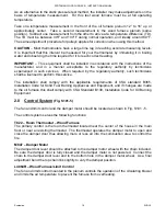
– For furnaces that use either the EVO (9200i) or MAX (9300i) controls, 

two extra 120 volt relays are required to interconnect the oil furnace to the wood furnace. If 
using the MAX (9300i) control, an AC/Auxiliary Temperature Sensor (Part # K00-KA-0090-F3) 
MUST be used, which is installed in the wood furnace plenum.  

DO NOT

 use the AC/Auxiliary 

temperature sensor with the EVO (9200i) and a wood furnace. 


2.7 DUCT 

CONNECTION

 (Fig. S101-5, Fig. S101-1)


See figure 

S101-16

 for 

Approved Furnace Ductwork Configurations.


See figure 

S101-17

 for 

Prohibited Furnace Ductwork Configurations. 


The use of A/C coils is not recommended unless special arrangements are made.


Minimum cross-sectional area of ductwork from furnace should be approximately 180 sq. in. 
with equal or larger size for return air. 


Summary of Contents for DB-101

Page 1: ...RE INSTALLING FURNACE OR LIGHTING FIRE CONSULT LOCAL AUTHORITIES IF IN DOUBT ABOUT YOUR LOCAL FIRE SAFETY REGULATIONS ALL INSTALLATIONS MUST BE MADE IN ACCORDANCE WITH LOCAL AND STATE OR PROVINCIAL CO...

Page 2: ...t 17 Appendices APPENDIX A Warranty DIAGRAMS S101 1 Add On to Oil Clearances S101 2 Add On to Oil S type duct S101 3 Gravity Return Air Kit S101 4 Base for use on Combustible Floor S101 5 Controls Pla...

Page 3: ...h 36 Diameter 23 Secondary Heat Exchanger 14 gauge steel Fire Box Door Cast Iron 13 x 13 Warm Air Plenum 32 x 25 3 8 Return Air Plenum N A Air Filter Size 16 x 20 x 1 Blower Size G10 10 Blower Motor 1...

Page 4: ...anufactured logs compressed wood Before adding fuel to an existing fire turn up the thermostat for about five minutes or lift damper chain to hold damper fully open for about one minute before opening...

Page 5: ...s smoke pipe and chimney allowing large amounts of creosote to form To reduce creosote build up during periods of low heat requirements i e Spring and Fall it is recommended to fuel the wood furnace w...

Page 6: ...Cleaning should be done whenever there is more than 1 4 inch of build up on the heat exchanger or 3 inches of ash in the base If the wood furnace is to be left unused for an extended period of time m...

Page 7: ...the following precautions should be taken DO NOT shut off power The blower must be kept running to disperse excessive heat Manually close the damper door by unhooking the chain Check controls for pro...

Page 8: ...he cover is an option available from your Kerr dealer The kit must be installed on the cabinet side directly opposite to the entry of the blower or oil furnace S connection ductwork Manually open the...

Page 9: ...fuel within the above clearances or within the space required for charging and ash removal o Establish a routine for storage of fuel care of the appliance and firing techniques 2 0 INSTALLATION INSTRU...

Page 10: ...ig S101 4 The location of the furnace must be as close as possible to the tile lined brick chimney or factory built solid fuel approved chimney ULC S629 Keep in mind also the day to day operation and...

Page 11: ...e flue gases are forced to fully heat the secondary heat exchanger which will maintain higher furnace efficiency The furnace must be located to meet a minimum venting distance needed between the furna...

Page 12: ...lue key pipe dampers and check draft controls located on or in the flue pipe 4 The flue pipes of the appliances are connected to a manifold as close to the chimney as practicable or directly to the ch...

Page 13: ...duct a 2 51 mm minimum clearance must be maintained between the warm air supply ducts and all joists or combustible material See Fig S101 1 Return air ducts including main ducts and branch ducts on s...

Page 14: ...m the yellow wire leading to the blower compartment and both red and yellow wires marretted off then there would be no need for the switching relay Honeywell R4222D 1013 or equiv In that case the two...

Page 15: ...end of the wire on to the other side of the normally open contacts relay spade 3 8 Remove the yellow low speed wire from the blower motor this should be the selected low speed in the furnace wiring bo...

Page 16: ...a reverse flow is possible Before attempting installation determine if there is suitable space available in the furnace area for the furnace connection outlined herein The external static pressure in...

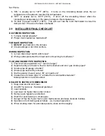
Page 17: ...h technicians shall be licensed to perform this service The installation shall comply with the applicable requirements of CSA standard B365 Installation Code for Solid Fuel Burning Appliances and Equi...

Page 18: ...s main disconnect switch within view 2 Wiring cables protected from heat and not touching hot surfaces FLUE AND SMOKE PIPE INSPECTION 1 Flue inner size equivalent to 7 round or larger 2 Separate entry...

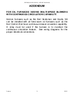
Page 19: ...ON CAPABILITY Add on furnaces such as the Kerr Scotsman and Scotty SS can be installed with oil fired warm air furnaces such as the Kerr Gemini that have continuous blower circulation capability A rel...

Page 20: ......

Page 21: ......

Page 22: ......

Page 23: ......

Page 24: ......

Page 25: ......

Page 26: ......

Page 27: ......

Page 28: ......

Page 29: ......

Page 30: ......

Page 31: ......

Page 32: ......

Page 33: ......

Page 34: ......

Page 35: ......

Page 36: ......

Reviews: