6
Control elements, displays and connections
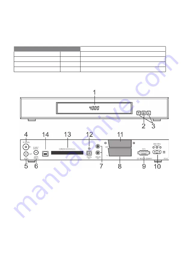
Front of the device
1 Display or LED:
Display
LED
-
red
Receiver is on standby
Programme display
green
Receiver is switched on
rEC.
Timer is activated
FAIL
Short circuit or overload at antenna socket
2
ON/OFF button (standby)
3
Buttons for changing programme:
W
programmes down,
V
programmes up
g g
g
g
g
Rear of the device
4
VHF/UHF digital input – antenna socket for house or indoor antenna.
5
HF output – for connecting an HF cable to the antenna socket of a television
or video recorder.
6
IF input digital – connection for the LNB of your satellite antenna.
7
AUDIO L/R cinch sockets to connect the receiver to an amplifi er.
8
TV scart socket to connect the receiver to a television.
9
Serial interface to connect to a PC, to be able to use the receiver’s
additional PC-controlled functions.
10
Mains socket to connect the mains cable supplied.
11
VCR scart socket to connect a video recorder.
12
Optical sockets for DOLBY DIGITAL signals
13
Common Interface shaft for inserting Conditional Access Modules.
14
USB 2.0 socket to connect to a PC (optional for hard disk devices).


