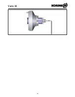
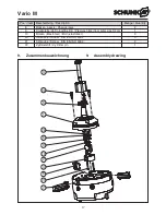
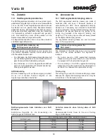
background image

18

Vario M

10. Zubehör

10.1 SAD Segmentspannbüchse

Die SAD Segmentspannbüchsen sind aus einem durch-
gehärtetenStahl gefertigt und haben eine Rockwellhärte
von ca. 55 HRC. Diese Segmentspannbüchsen können
bei Bedarf auf den gewünschten Spanndurchmesser
abgedreht werden. Die Segmentspannbüchse wird auf
das gewünschte Maß abgedreht indem der Abdrehring
(im Lieferumfang enthalten) aufgesetzt und gespannt
wird. Der Abdrehring muss dabei gerade auf die
Segmentspannbüchse aufgesetzt werden.

Die Segmentspannbüchse kann nun auf das erforderli-
che Maß abgedreht werden.

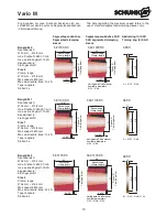
Vorsicht beim Abdrehen der
SAD-Segmentspannbüchse!

Der Durchmesser der SAD-Büchse darf maximal bis
zum Gummi abgedreht werden, wobei dieser selbst
nicht bearbeitet werden darf.

– Das Abdrehen der SAD Segmentspannbüchse darf

aus Sicherheitsgründen nur auf einer Maschine mit
geschlossener Schutzabdeckung erfolgen.

– Das Abdrehen von SAD Segmentspannbüchsen

darf nur von Facharbeitern mit entsprechender Aus-
bildung durchgeführt werden.
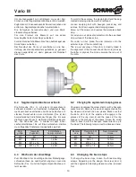
ABR Abdrehring

Mit dem Abdrehring wird ein Spannvorgang simuliert,
da es nur in diesem Zustand möglich ist, die
Segmentspannbüchse abzudrehen.

10. Accessories

10.1 SAD segmented clamping sleeve

The SAD segmented clamping sleeves are made of
hardened steel and have a Rockwell hardness of
approximately 55 HRC. These segmented clamping
sleeves can, if necessary, be untwisted to the desired
clamping diameter. The segmented clamping sleeve is
untwisted to the desired dimension by putting on the
turning ring (included in the scope of delivery) and
clamping it. The turning ring must be just barely placed
on the segmented clamping sleeve.

The segmented clamping sleeve can now be turned
down to the required size.

Caution when turning down the
SAD sleeve!

The diameter of the SAD sleeve can only be turned
down until the rubber between the segments is
reached.

– For safety reasons, SAD segmented clamping

sleeve must only be turned down on a machine that
is equipped with closed protective guards.

– The machining of the SAD segmented clamping

sleeves must only be turned down by skilled person-
nel which has received the appropriate training.

Turning ring

The turning ring is used to simulate a clamping process
because the segmented clamping sleeve can only be
turned down in the clamped position.
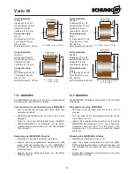
HINWEIS

NOTICE

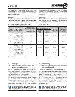
Betätigungsmomente beim Abdrehen von SAD-
Büchsen

Empfohlene Zugkräfte für die Verwendung von
Abdrehringen bei SAD Büchsen.

Actuation moments when turning down of SAD
sleeves

Recommended tensile forces for the use of turning
rings in SAD sleeves.

ROTA-S vario

Max. Betätigungsmoment / Max. actuation moment

200-52

200-62

M0

15 Nm

15 Nm

M1

15 Nm

15 Nm

M2

30 Nm

30 Nm

M3

––

45 Nm

Summary of Contents for Vario M

Page 1: ... M 08 Vario M de en Montage und Betriebsanleitung Assembly and Operating manual Segmentspanndorn Vario M Ergänzung zu ROTA S vario Segmented mandrel Vario M Supplement to ROTA S vario Dokument Stand 2013 11 06 ...

Page 2: ...nfo cz schunk com www cz schunk com DENMARK SCHUNK Intec A S Tel 45 43601339 Fax 45 43601492 info dk schunk com www dk schunk com FINLAND SCHUNK Intec Oy Tel 358 9 23 193861 Fax 358 9 23 193862 info fi schunk com www fi schunk com FRANCE SCHUNK Intec SARL Tel 33 1 64663824 Fax 33 1 64663823 info fr schunk com www fr schunk com GREAT BRITAIN SCHUNK Intec Ltd Tel 44 1908 611127 Fax 44 1908 615525 in...

Page 3: ...nisatorische Maßnahmen Organisational measures 9 4 Lieferumfang Scope of delivery 11 5 Produktbeschreibung Product description 11 6 Montage Assembly 12 6 1 Anbau des Segmentspanndornes auf das Handspannfutter Mounting the segmented mandrel on the manual chuck 12 6 2 Segmentspannbüchse wechseln Changing the segmented clamping sleeve 14 6 3 Wechseln der Anschläge Changing the back stops 14 6 4 Zerle...

Page 4: ...dere Wettbewerbsfirmen zugänglich gemacht werden 1 5 Technische Änderungen Änderungen im Sinne technischer Verbesserungen sind uns vorbehalten 1 About this manual 1 1 Purpose Validity This manual is part of the SCHUNK segmented man drel Vario M and describes the reliably and proper use during all phases of operation This manual is valid only for the SCHUNK segmented mandrel Vario M 1 2 Target grou...

Page 5: ... Sicherheit des Segmentspanndorns nicht zu beeinträchtigen Bei Nichteinhaltung entfällt der weitere Gewährleistungsanspruch 2 General 2 1 Warranty The warranty period is 24 months after delivery date from factory assuming appropriate use in single shift operation max 50000 cycles and respecting the rec ommended maintenance and lubrication intervals Basically all seals sealing elements screw connec...

Page 6: ... verbunden sein Die angege benen maximalen technologischen Daten dürfen dabei nicht überschritten werden Please note that we cannot accept any liabil ity for damage caused by not observing this Operating Manual 2 3 Documentation A product specific documentation is supplied as part of the scope of delivery of the segmented mandrel de signed and manufactured by SCHUNK GmbH Co KG It is the responsibi...

Page 7: ...svorschriften kann Gefahr für Leib und Leben des Bedieners drohen The segmented mandrel should only be used on the basis of its technical data This also comprises the observance of the conditions of initial operation assembly operation as well as conditions of environ ment and maintenance provided by the manufacturer For each individual clamping task the permitted rota tional speed and the necessa...

Page 8: ...Original SCHUNK Ersatzteile ersetzt werden WARNING Irrespective of whether our segmented man drel are used under rotation or stationary it is mandatory to wear protective equipment in accordance with the EC machine guide line so that loose parts discharged in case of the chuck or a component malfunctioning are absorbed by the protective equipment The machine manufacturer must ensure that there is ...

Page 9: ...ln von den Personen die mit der Bedienung Wartung und Instandsetzung des Segmentspanndorns betraut sind beachtet werden Check the segmented mandrel at least once per shift for externally visible damage and faults Only restart the machine to which the segmented mandrel is fitted when the cause of the problem has been eliminated Technical condition The segmented mandrel may only be used in a techni ...

Page 10: ... durchführen lassen das im Sinne der Sicherheitsvorschriften als Sachkundiger gelten kann Supervision of conduct The business operator is required at least from time to time to check personnel s conduct regarding awa reness of safety and hazards Hazard notices The business operator must ensure that the notes of safety and hazards for the machine to which the seg mented mandrel is mounted are obser...

Page 11: ...rn wird Stirnseitig auf dem Handspann futter aufgeschraubt und durch dessen Betätigung über einen Drehmomentschlüssel gespannt Dabei bewegen sich die Backen im Futter Also determine an operator who is responsible for safety conscious conduct Enable him to refuse instructions by third parties who which are irrespon sible with regard to safety During training and instruction period the person nel mu...

Page 12: ...nts 0 25 30 Nm 30 Nm 20 kN 85 kN M3 von Ø 50 bis Ø 80 1 mm steigend from Ø 50 to Ø 80 1 mm increments 0 35 45 Nm 25 kN 105 kN 6 Montage 6 1 Anbau des Segmentspanndornes auf das Handspannfutter Pos Nr siehe Zusammenbauzeichnung in Kapitel 9 Der Segmentspanndorn wird montagefertig angeliefert Lediglich Zubehörteile wie die Segmentspannbüchse Anschlag usw sind noch zu montieren Der Segmentspanndorn V...

Page 13: ...he marking surface on the jaw is at the perimeter of the base body see Figure 2 5 Twist the manual chuck until the marking surface on the active jaw item 7 has completely disappeared under the base body item 1 6 The segmented clamping sleeve can now be installed see chapter 6 2 Bild Illustration 1 Bild Illustration 2 Demontage des Vario M Die Demontage vom Spannfutter erfolgt sinngemäß in umgekehr...

Page 14: ...chse entfernt werden Zugbolzen mit Innensechskantschlüssel losdrehen und entfernen Segmentspannbüche herunterziehen Die Schrauben herausschrauben und den Werk stückanschlag entfernen Für den Planlauf die Messuhr auf die axiale Anschlagfläche des Anschlags aufsetzen Für den Rundlauf die Messuhr auf den Außenkegel des Dornkörpers aufsetzen Der Rundlauf des Dorns ist unmittelbar an die Aus richtung d...

Page 15: ...he arbor is now disassembled Clean all parts and check all parts for damage and wear Only original SCHUNK spare parts must be used in replacement of damaged parts The segmented mandrel is mounted in reverse order accordingly 7 Trouble shooting Problem Mögliche Ursache Abhilfe Exzentrische Maßabweichung am Werkstück Rundlauffehler des Segmentspanndornes Rundlauf am Außenkegel des Dornes überprüfen ...

Page 16: ...iers of the ejector ring do not engage with the slots Fully tighten clamping bolt Clean the mandrel body and of the ejector ring Reposition segmented clamping sleeve 8 Ausführungen und Ersatzteile 8 Types and spare parts Bei Bestellung von Ersatzteilen ist es unumgänglich die Type Größe und vor allem die Fertigungs Nr des Futters anzugeben um Fehllieferungen zu vermeiden Grundsätzlich sind Dichtun...

Page 17: ...aws 2 9 Druckplatte ab Dorngröße D2 Pressure plate from arbor size D2 on 1 10 Bolzen Elastomer Bolt elastomer 3 20 Schraube Screw DIN EN ISO 4762 3 21 Schraube Screw DIN EN ISO 4762 2 22 Zylinderstift Cylinder pin 1 9 Zusammenbauzeichnung 9 Assembly drawing 2 7 9 5 3 22 6 21 8 4 10 1 20 ...

Page 18: ...hardened steel and have a Rockwell hardness of approximately 55 HRC These segmented clamping sleeves can if necessary be untwisted to the desired clamping diameter The segmented clamping sleeve is untwisted to the desired dimension by putting on the turning ring included in the scope of delivery and clamping it The turning ring must be just barely placed on the segmented clamping sleeve The segmen...

Page 19: ...amping sleeve Abdrehring für SAD Turning ring for SAD 1 x 30 D Spann Ø Clamping diam 26 Spannlänge Clamp length SB 110RØD 1 x 30 D Spann Ø Clamping diam 26 Spannlänge Clamp length SAD 110RØD Verfügbare Durchmesser Available diameters Ø 32 Ø 38 Ø A 10 ABR Ø A Ø 32 Ø 38 Ø B Baugröße 1 Spannbereich Ø 26 mm Ø 38 mm max Drehzahl 48000 1 min max axiale Zugkraft 10 kN Kegelwinkel 6 3fach geschlitzt Size ...

Page 20: ...e Zugkraft 25 kN Kegelwinkel 6 6fach geschlitzt Size 3 Clamp range Ø 50 mm Ø 80 mm Max speed 4200 rpm Max axial tensile force 25 kN Taper angle 6 Slotted 6 x Segmentspannbüchse Segmented clamping sleeve Segmentspannbüchse SAD SAD segmented clamping sleeve Abdrehring für SAD Turning ring for SAD 10 2 Anschläge Standard Anschläge Die Anschläge sind als Zubehör erhältlich und nicht Bestandteil des Se...

Page 21: ...Remove the clamping bolt as usual Insert the supplied withdrawal tool into the MAN DREX cartridge and tighten it with an Allen key until the cartridge can be removed from the mandrel body Loosen the withdrawal tool and remove it from the MANDREX cartridge Ø D Außen Ø OD Gesamtlänge Total length D Ø 20 5 Ø 24 5 Ø 28 5 variabel variable P LK Ø D Außen Ø OD Gesamtlänge Total length D Ø 26 5 Ø 32 5 Ø ...

Page 22: ...22 Vario M ...

Page 23: ...ons the ope rating instructions in particular the section on Safety Operator Date Business Operator Date Authorized person Kenntniserklärung des beauftragten Personals Bediener Hiermit bestätigt die vom Betreiber Anwender beauftragte Person Herr Frau die innerbetrieblichen Anweisungen die Betriebsanleitung insbesondere das Kapitel Sicherheit gelesen und ver standen zu haben Bediener Datum Betreibe...

Page 24: ...ondere DIN EN 1550 Sicherheit von Werkzeugmaschinen Sicherheitsanforderungen für die Ge staltung und Konstruktion von Spannfuttern für die Werkstückaufnahme DIN 55028 Werkzeugmaschinen Aufnahmen für Spannzeuge EN ISO 12100 1 Sicherheit von Maschinen Grundbegriffe allgemeine Gestaltungsleitsätze Teil 1 Grundsätzliche Terminologie Methodik EN ISO 12100 2 Sicherheit von Maschinen Grundbegriffe allgem...

Page 25: ...6 42 EC is confirmed Applied harmonized standards especially DIN EN 1550 Machine tools safety Safety requirements for the design and constructions of work holding chucks DIN 55028 Machine tools holding fixtures for clamping devices EN ISO 12100 1 Safety of machinery Basic concepts general principles for design Part 1 Basic terminology methodology EN ISO 12100 2 Safety of machinery Basic concepts g...

Reviews: