


Assembly
16
03.00|KSF plus, KSF-LH plus, KSF-F plus |en
•
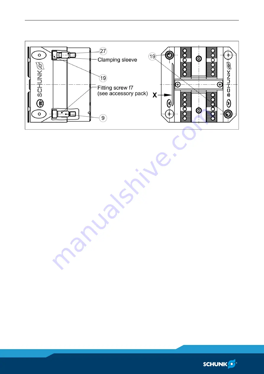
Surface
"X"
is parallel to the guideway of the base jaws (item 2)
so that the clamping block can be aligned on the machine table.
Assembling the clamping block
Assembly with clamping sleeves:
the clamping block is mounted on the machine table together
with clamping sleeves (item 27) and screws (item 19).
Assembly with fitting screws:
There are two fittings in the housing (item 1) that, along with the
optional fitting screws (item 9), are used to center the clamping
block on the machine table with repeat accuracy. Do not realign
the clamping block after removing it from the machine table (e.g.,
after replacing the seals). When using fitting screws (item 9), use
them instead of the clamping sleeves (item 27) and the two
corresponding screws (item 19).


