


Assembly and Commissioning
12.03|SRU 20 - 60|en
15
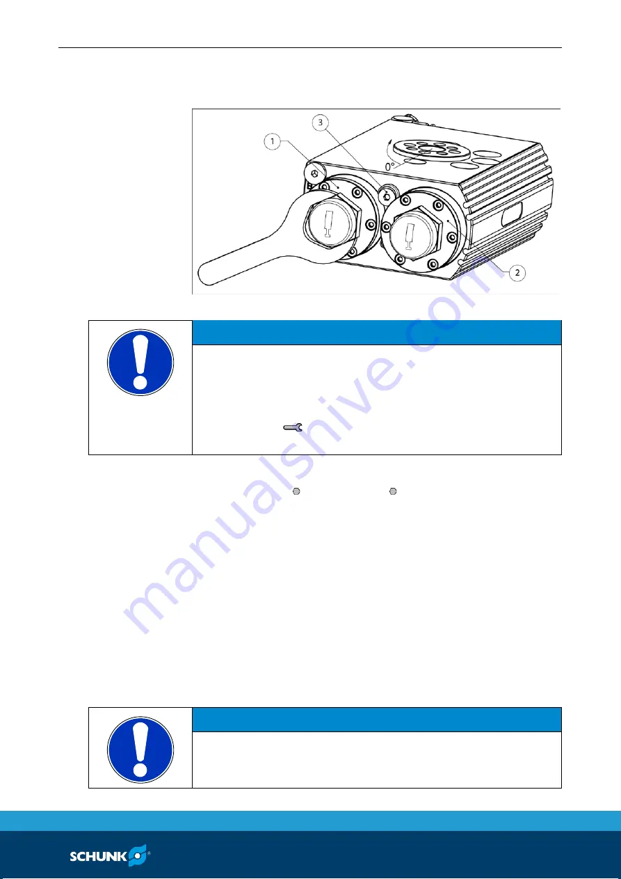
Adjusting the end positions
Fig. 4
Basic setting
NOTICE
The end positions should not be changed by turning the axial
hexagon socket at the face, or by turning the clamping nut or
the shock absorber (VM-versions).
This way the individual components can be unscrewed.
• Please use a
19 (SRU 20 – 25) or 32 (SRU 30 – 60), which is
positioned at the hexagon of the stop cover
1 Loosen bolt (3) approx. one turn using hexagon socket wrench
(SRU 20 – 40: 4, SRU 50 – 60: 5).
2 Apply air to connection "B". Unit swivels to stop A (1) (basic
setting 0°).
3 Set the desired end position by turning stop A.
(For SRU 50-60; depressurize before adjusting)
4 Vent connection B and apply air to A.
The unit swivels to stop B (3)(basic setting 180°).
5 Set the required limit position by rotating stop B (3).
(For SRU 50-60: depressurize before adjusting)
6 Tighten Screws (2) fully.
(SRU 20-40: 10Nm; SRU 50-60: 24Nm)
7 Swivel repeatedly to test the limit position setting.
NOTICE
The limiting sleeves (depending on the variant item 7, 10 , 25)
limit the adjustment range of the stops. For safety reasons, the
unit shoud only be operated with mounted limiting sleeves.
6.3