


Assembly and Commissioning
12.03|SRU 20 - 60|en
13
1
2
3
4
6
5
7
8
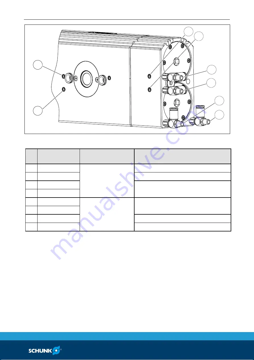
Fig. 3
compressed air connections A, B, C and D
Ite
m
Designation
Description
Function
1
b
Hose-free
direct connection
Swiveling 90° - 0° / 180° - 0°
2
a
Swiveling 0° -90° / 0° - 180°
3
d
Approach center position (M)
Extend locking piston (VM)
4
c
5
C
Hose connection
Approach center position (M)
Extend locking piston (VM)
6
D
7
A
Swiveling 0° -90° / 0° - 180°
8
B
Swiveling 90° - 0° / 180° - 0°
Pay attention to the following table when using flow controls.
1 The air connections labeled "C" and "D" must be pressurized
simultaneously (with a t-joint).
Air connection for
variants with
center position (M)