Assembly
22
08.00 | PZN-plus | Assembly and Operating Manual | en | 0389374
Item
160
200
240
300
380
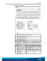
Mounting the product from the front (side A)
1
Mounting screw (3 x)
M8
M10
M12
M16
M20
Mounting the product from the rear (side B)
2
Mounting screw (3 x)
M10
M12
-
-
-
Max. depth of engagement
from locating surface [mm]
without gripping force
maintenance
21.5
25
-
-
-
Max. depth of engagement
from locating surface [mm]
with gripping force
maintenance (AS / IS)
51.5
61
-
-
-
3
Fitting bore for cylindrical
pins *
Ø6H7
Ø8H7
Ø8H7
Ø10H7 Ø12H7
Possible recess in the adapter plate
A
Max. recess [mm]
Ø115
Ø150
Ø196
Ø236
Ø292
Affixing the gripper fingers
4
Mounting screw(2x)
M10
M12
M12
M16
M20
Max. depth of engagement
from locating surface [mm]
17
17
20
26
30
5
Centering sleeve * [mm]
Ø14
Ø16
Ø16
Ø22
Ø28
*) Contained in accessory pack.
5.2.1.1 Mounting of the gripper by using a spring loaded pressure-piece
CAUTION
The spring-loaded pressure piece is under spring tension.
The pressure piece can fly out in an uncontrolled fashion and
cause contusions.
•
During assembly or disassembly, be especially careful with the
springs.
When mounting the gripper from the side of the gripper fingers,
the assembly of the pressure piece must be done
after
the mount-
ing of the gripper.
Mounting the pressure piece is described in the insert "Installation
instructions - pressure piece", which is included in the pressure
piece's scope of delivery.


