8
Montage- und Betriebsanleitung
für 2-Backen-Parallelgreifer Type PGN
Assembly and Operating Manual for
for 2-Finger-Parallel-Gripper Type PGN
ACHTUNG!
Bei der Ausführung »Außengreifkraftsicherung mit
Feder« kann der Deckel (Pos. 36) durch einen Defekt
unter Federspannung stehen. Spannen Sie vorsich-
tig den Greifer zwischen dem Gehäuse (Pos. 50) und
Deckel (Pos. 36) ein (siehe Kapitel 9). Entfernen Sie
die Schrauben (Pos. 40) und entspannen Sie lang-
sam. Nehmen Sie den Deckel (Pos. 36) ab.
Spannen Sie den Greifer vorsichtig wieder zwischen
Gehäuse (Pos. 50) und dem Zylinderkolben (Pos. 37)
ein. Entfernen Sie die Schraube (Pos. 39) und ent-
spannen Sie langsam, bis die Feder entspannt ist.
Fahren Sie fort wie beim Greifer ohne Greifkraftsicherung (von
Punkt 5 bis 8).
Der Zusammenbau erfolgt in umgekehrter Reihenfolge.
Montieren Sie den Greifer bis auf die Schrauben (Pos. 39 und
40), den Deckel (Pos. 36), die Feder (Pos. 41) und den
Zylinderkolben (Pos. 37).
Diese Teile können nur mit einer Montagevorrichtung
montiert werden.
Zeichnungen
und
Maße
der
Montagevorrichtung
siehe
Kapitel 11.
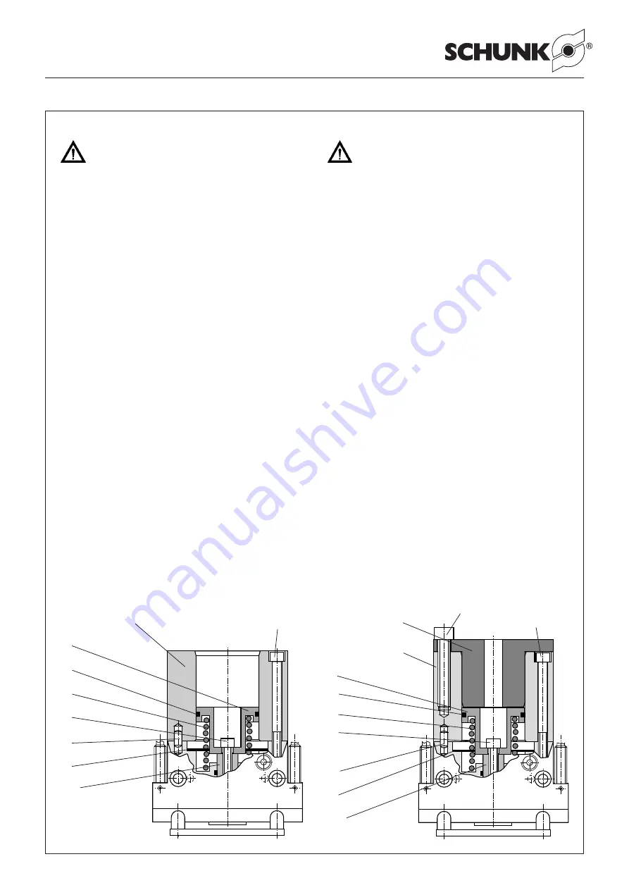
Der Zusammenbau mit der Montagevorrichtung ist nachfolgend
ausführlich beschrieben.
Beachten Sie dabei die Hinweise 2, 3 und 6 in Abschnitt 7.1 und
die Schraubenanzugsmomente (Seite 9).
Montage mit Vorrichtung für
PGN 50, 64, 125 und 160:
1. Backen und Futterkolben montieren. Legen Sie danach die
Feder der Greifkraftsicherung (Pos. 41) ein.
2. Vorrichtung 1 aufsetzen und montieren.
3. Zylinderkolben (Pos. 37) ohne Dichtung vorsichtig in die
Vorrichtungsbohrung einsetzen und bis auf die Feder
(Pos. 41) drücken.
4. Schraube (Pos. 39) einlegen und mit dem geforderten Dreh-
moment anziehen (siehe Tabelle Seite 9).
5. Vorrichtung(en) entfernen.
6. Dichtung (Pos. 13) vorsichtig auf das Gehäuse aufbringen.
7. Zylinderkolbendichtung (Pos. 14) aufziehen.
8. Deckel (Pos. 36) montieren.
CAUTION!
In case of the version ”with Gripping Force Safety
Device with Spring for O.D. gripping“ the cover
(item 36) may be under spring pressure if it should be
dammaged. Carefully clamp the gripper between
housing (item 50) and cover (item 36) (see chapter 9).
Remove the screws (item 40) and slowly unclamp.
Put off the cover (item 36) now. Carefully clamp the
gripper between housing (item 50) and cylinder
piston (item 37) again. Remove screw (item 39) and
slowly unclamp until the spring is in relaxed position.
Proceed the same way as for the gripper without gripping force
safety device (from Point 5 – 8).
Assembly is done in reverse order.
Assemble the gripper except the screws (item 39 and 40), the
cover (item 36), the spring (item 41) and the cylinder piston
(item 37).
These parts can only be assembled with an assembly
device.
For drawings and dimensions of the mounting device see chap-
ter 11.
Assembly together with the mounting device is described below
in detail.
Consider the notes 2, 3 and 5 of chapter 7.1 and the screw
tightening torques (page 9).
Assembly with an assembly device for
PGN 50, 64, 125 and 160:
1 Assemble the jaws and the chuck piston. Then put the spring
for the gripping force safety device (item 41) into it.
2. Put on the device and assemble.
3. Carefully insert the cylinder piston (item 37) without seal
into the device bore and push it until it contacts the spring
(item 41).
4. Insert the screw (item 39) and thighten it with the required tor-
que (see chart on page 9).
5. Remove the device(s).
6. Carefully place the seal (item 13) onto the housing.
7. Locate the seal of the cylinder piston (item 14).
8. Assemble the cover (item 36).
Vorrichtung 1
Mounting device 1
Schraube 1
Screw 1
37
14
41
39
51
3 / 8
13
Vorrichtung 1
Mounting device 1
Vorrichtung 2
Mounting device 2
37
14
41
39
51
3 / 8
13
Schraube 1
Screw 1
Schraube 2
Screw 2


