23
Montage- und Betriebsanleitung
für 2-Backen-Parallelgreifer Type PGN
Assembly and Operating Manual for
for 2-Finger-Parallel-Gripper Type PGN
Wir arbeiten ständig an der Verbesserung unserer Produkte. Deshalb sind die veröffentlichten Abmessungen und Angaben unverbindlich.
We constantly try to improve our products. Therefore all drawings and information given are subject to chance.
Betrieb mit einem Schließer- und einem Öffner-
Näherungsschalter
In einer früheren Version des PGN wurde standardmäßig mit
einem Öffner die Stellung »geöffnet« und mit einem Schließer die
Stellung »geschlossen« abgefragt.
Sollten Sie einen Greifer dieser Bauart durch einen neuen
ersetzen, jedoch die beiden bereits vorhandenen Sensoren
(1x Schließer, 1x Öffner) weiter benutzen wollen, so verfahren
Sie bitte folgendermaßen:
Schließer-Öffner-Abfrage
Der Zustand »Geöffnet« wird mit dem Öffner abgefragt, der
Zustand »Geschlossen« mit dem Schließer. Dazu muss die lange
Schaltnocke auf der Seite des Öffners um 180° gedreht werden.
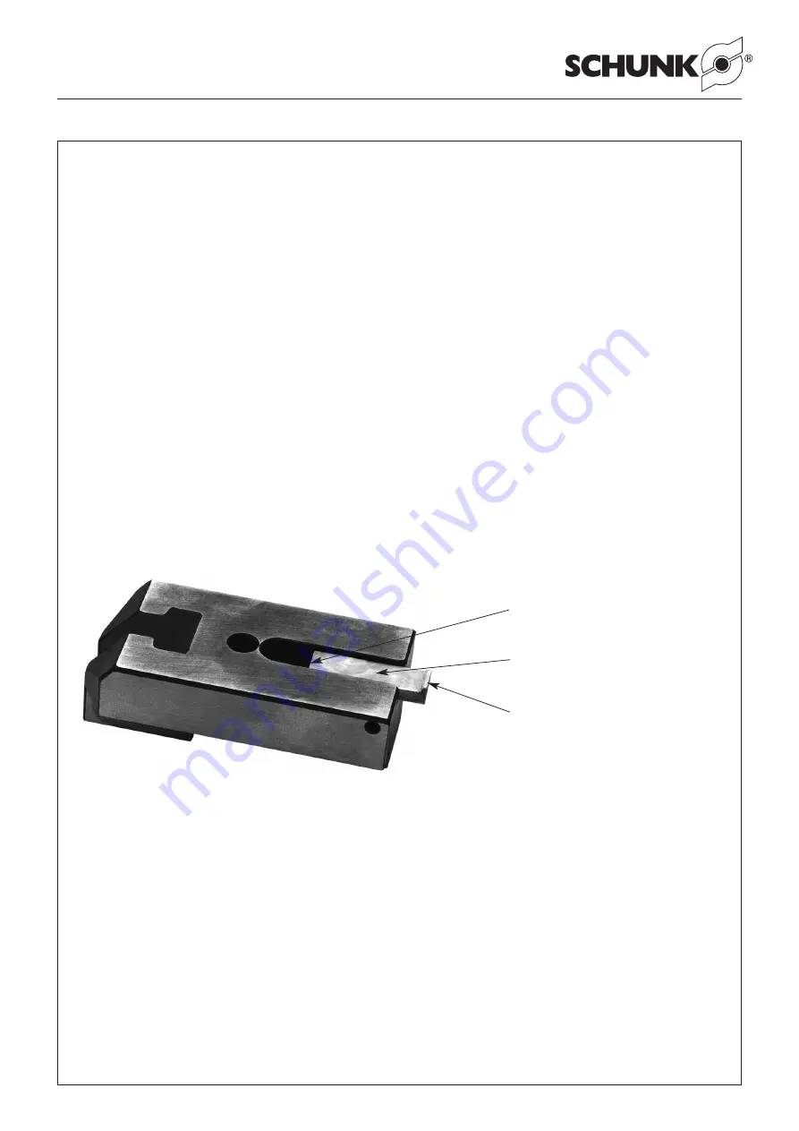
Die Nase ist nun nicht mehr dem Keilhaken zugewandt sondern
befindet sich außerhalb der Grundbacke (siehe Bild).
Die Position des Öffner-Sensors wird nun so eingestellt, dass er
den größtmöglichen Abstand zur Schaltnocke hat, jedoch gerade
noch bedämpft wird und daher kein Signal liefert, solange sich
der Bereich
B
der Schaltnocke vor ihm befindet.
Erst wenn sich der Greifer komplett geöffnet hat und sich so die
Kante
K
der Schaltnocke an ihm vorbei bewegt hat, liefert er sein
Ausgangssignal. Die Kante
K
gibt damit den Schaltpunkt des Öff-
ners vor.
Die Abfrage des Zustandes »Gegriffen« ist gleich wie bei
Schließer-Schließer-Abfrage.
Nach einer ersten Einrichtung der Schaltnocken sind diese auf
den genauen Schaltpunkt nachzujustieren.
Bei Greifern, die innen greifen, wird mit der langen Schaltnocke
der Zustand »Gegriffen« abgefragt, mit der kurzen Schaltnocke
der Zustand »Geschlossen«. Alles weitere verhält sich analog.
Je nach Greifer und abzufragender Position kann die lange
Schaltnocke aus dem Gehäuse herausstehen und zur Störkontur
werden. In diesem Fall kann sie gekürzt werden.
In case of grippers used for I.D. gripping, the status "gripped" is
monitored with the long control cam and the status "closed" with
the short one. All the other functions are working in the same
way.
Depending to the gripper and the monitored position, the long
control cam may overhang from the housing and be an interfering
contour. In this case the control cam should be shortened.
Operation with a closing and opening proximity
switch
In an old standard version of the PGN, the "open" position was
monitored with an opener and the "closed" position with a closer.
If you should intend to replace a gripper of this version by a new
version, however the exisiting sensors (1x closer, 1x opener)
should still be used, please proceed as follows:
Closed-open monitoring
The position "open" is monitored by an opener, the position "clo-
sed" by a closer. The long control cam at the side of the opener
has just to be turned by 180°. The nose is no longer turned
towards the wedge hook, but is located outside the base jaw (see
illustration).
The position of the opening sensor is adjusted now in a way, that
it has the largest possible distance to the control cam, is still
actuated and therefore doesn't furnish a signal while it traverses
area
B
of the control cam.
An output signal is not furnised until the gripper completely opend
and edge
K
of the control cam has been passed. Edge
K
there-
fore determines the switching point of the opening sensor.
Monitoring the status "Gripped" is the same as monitoring "clo-
sed" status of a closer.
After the initial adjustment of the control cam, the exact switching
points have to be re-adjusted.
Kante
K
der Schaltnocke
Edge
K
of the control cam
Ebener Bereich
B
der Schaltnocke
Even range
B
of the control cam
Nase
Nose


