


7
Montage- und Betriebsanleitung
für Schwenkeinheit Type OSE 22
Assembly and Operating Manual for
for Swivel Unit Type OSE 22
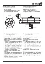
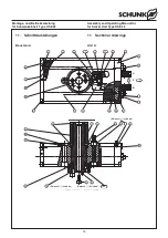
Ansicht
X
View
X
1
2
4
3
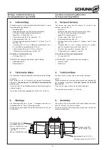
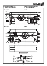
Drehdurchführung:
(Zubehör, nur bei Bestellung der Schwenkeinheit möglich)
Maße für schlauchlosen Direktanschluss am Ritzel:
für O-Ring 2.5 x 1 (Pos. 52)
Rotary transmission lead through:
(Accessory, only possible if indicated on your order)
Dimensions for direct connecttion without hoses at the pinion:
for O-ring 2.5 x 1 (item 52)
4
Y
2
0.7
4
.4
2
.5
1
2
3
4
7.
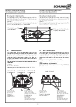
Montage und Einstellung der
Näherungsschalter
(siehe Abbildungen Kapitel 11, nur auf besondere Bestellung):
Benötigen Sie mehr Informationen über die Handhabung von
Sensoren, wenden Sie sich vertrauensvoll an Ihren SCHUNK-
Ansprechpartner oder nutzen Sie unsere Download-Möglich-
keiten unter
www.schunk.com > Produkte > Automation > Zubehör
Baustein A und B:
–
Stellen Sie die Schnellspannhülsen (Pos. 21a) so ein, dass
sie von den vorbeischwenkenden Schaltnocken etwa 0,5 mm
Abstand haben. Klemmen Sie die Hülse dann mit dem
Gewindestift (Pos. 21b) leicht.
–
Lösen Sie den Gewindestift am Schaltnocken (Pos. 23)
ca. 1/2 Umdrehung, damit der Nocken sich verschieben lässt.
–
Beaufschlagen Sie den Anschluss bei A, bis die Schwenk-
einheit ihre Endstellung erreicht hat. Schieben Sie jetzt die
Schaltnocke, bis der Schalter bei B beaufschlagt ist.
–
Drehen Sie das Ritzel aus dieser Stellung und ziehen Sie den
Gewindestift an der Schaltnocke wieder an.
Die Einstellung für die andere Endstellung erfolgt analog.
Baustein C:
Die Schaltnocke wird in die Nut montiert, die durch Aufschrauben
der Klemmscheibe C (Pos. 19 bzw. 18) auf dem Ritzel entsteht.
Der Näherungsschalter zur Abfrage der Zwischenstellung wird
durch die Klemmbrücke (Pos. 22) gehalten.
Stellen Sie den Schalter so ein, dass er von der vorbei-
schwenkenden Schaltnocke ca. 0.5 mm Abstand hat. Klemmen
Sie dann den Schalter mit der Schraube (Pos. 75).
7.
Assembly and adjustment of the
proximity switch
(see illustrations chapter 11, only if ordered separately):
If you would like more information on the operation of sensors,
please contact your SCHUNK representative. Information is also
available for download at
www.schunk.com>Products>Automation>Accessories
Module A and B:
–
Adjust the quick action bushing (item 21a) in a way that the
passing control cams have a distance of 0.5 mm. Slightly
clamp the bushing with a set-screw (item 21b).
–
For being able to move the cam, loosen the set-screw at the
control cam (item 23) appr. by half a rotation.
–
Actuate connection A until the swivel units arrives at its end
position. Move the control cam now until the switch is actua-
ted at B.
–
Turn the pinion out of this position and thighten the set-screw
at the control cam again.
Adjustment of the other end position is done the same way.
Module C:
The control cam is mounted in the groove, which emerges
from the unscrewing of the clamping disk C (item 19 or 18) at
the pinion. The proximity switch is supported by the clamping
pieces (item 22) during monitoring of the intermediate position.
Adjust the switch in a way that the passing control cams have a
distance of 0.5 mm. Clamp the switch with a screw (item 75).
X
3
1


