


1.
Sicherheit
1.1 Symbolerklärung
Dieses Symbol ist überall dort zu finden wo
besondere Gefahren für Personen oder Beschädi-
gungen der Einheit möglich sind.
1.2 Bestimmungsgemäßer Gebrauch
Das Produkt ist zum Ein-/Anbau für Maschinen bzw. Anlagen be-
stimmt. Die Anforderungen der zutreffenden Richtlinien müssen
beachtet und eingehalten werden.
Das Produkt darf ausschließlich im Rahmen seiner technischen
Daten verwendet werden.
Ein darüberhinausgehender Gebrauch gilt als nicht bestim-
mungsgemäß. Für Schäden aus einem solchen Gebrauch haftet
der Hersteller nicht.
1.3 Umgebungs- und Einsatzbedingungen
–
Die Einheit nur innerhalb der im Technischen Katalog defi-
nierten Einsatzparameter einsetzen. Es gilt jeweils die letzte
Fassung (lt. Kapitel 2.3 AGB). Bitte prüfen Sie, ob Ihr Ein-
satzfall anhand des aktuellen SCHUNK-Berechnungs-
programms geprüft wurde. Ist dies nicht der Fall, kann keine
Gewährleistung übernommen werden.
–
Anforderung an die Druckluftqualität nach ISO 8573-1: 6 4 4.
–
Vorraussetzung sind saubere Umgebungsbedingungen bei
Raumtemperatur. Sollte dies nicht eingehalten werden, ver-
ringert sich je nach Anwendungsfall das Wartungsintervall.
–
Die Umgebung muss frei von Spritzwasser und Dämpfen,
sowie von Abriebs- oder Prozessstäuben sein. Ausgenommen
hiervon sind Einheiten, die speziell für verschmutzte Umge-
bungen ausgelegt sind.
1.4 Sicherheitshinweise
1.
Die Einheit ist nach dem Stand der Technik zum Zeitpunkt der
Auslieferung gebaut und betriebssicher. Gefahren können von
ihr jedoch ausgehen, wenn z.B.:
die Einheit unsachgemäß eingesetzt, montiert, gewartet oder
zum nicht bestimmungsgemäßen Gebrauch eingesetzt wird.
die EG-Maschinenrichtlinie, die UVV, die VDE-Richtlinien, die
Sicherheits- und Montagehinweise nicht beachtet werden.
2.
Jeder, der für die Montage, Inbetriebnahme und Instand-
haltung zuständig ist, muss die komplette Betriebsanleitung,
besonders das Kapitel 1 »Sicherheit«, gelesen und verstan-
den haben. Dem Kunden wird empfohlen, sich dies schriftlich
bestätigen zu lassen.
3.
Der Ein- und Ausbau, die Montage der Näherungsschalter,
das Anschließen und die Inbetriebnahme darf nur von auto-
risiertem Personal durchgeführt werden.
4.
Arbeitsweisen, die die Funktion und Betriebssicherheit der
Einheit beeinträchtigen, sind zu unterlassen.
5. Keine Teile von Hand bewegen, wenn die Energie-
versorgung angeschlossen ist.
6. Nicht in die offene Mechanik und den Bewegungs-
bereich der Einheit greifen.
1.
Safety
1.1 Symbol key
This symbol is displayed wherever there is a
danger of injury or where the unit may suffer
damage.
1.2 Appropriate use
The unit is intended for installation / mounting for machinery and
equipment. The requirements of the applicable directives must be
observed and complied with.
The unit may only ever be employed within the restrictions of its
technical specifications.
Using the system with disregard to even a minor specification will
be deemed inappropriate use. The manufacturer assumes no lia-
bility for any injury or damage resulting from inappropriate use.
1.3 Environmental and operating conditions
–
Use the unit only within the application parameters defined in
the Technical Catalog. The most recent version applies (ac-
cording to the General Terms and Conditions). Please make
sure that your application has been checked based on the cur-
rent SCHUNK calculation program. If this is not the case, we
can provide no warranty.
–
Standard for quality of the compressed air according to ISO
8573-1: 6 4 4.
–
Clean ambient conditions at room temperature are required. If
these conditions are not ensured, the maintenance interval will
be shorter, depending on the actual utilization.
–
The environment must be free of splashing water and vapors,
and also of abrasive dust and process dust. This does not
apply to units designed especially for dirty environments.
1.4 Safety information
1.
The unit is built according to the level of technology available
at the time of delivery and is safe to operate. However, the unit
may still be dangerous if, for example:
the unit is used, assembled or maintained inappropriately or is
used for purposes other than those it is intended for.
the EC Machine Directive, the accident prevention regulations,
the VDE guidelines, or the safety information and assembly
instructions are not heeded.
2.
Any persons who may be responsible for assembly, commis-
sioning and maintenance of the unit are obliged to have read
and understood all of the operating instructions, in particular
chapter 1 “Safety”. We recommend that the customer have
this confirmed in writing.
3.
The installation, deinstallation, assembly of all motion detec-
tors, connection and commissioning may only be performed
by authorized, appropriately trained personnel.
4.
Modes of operation that adversely affect the function and/or
the operational safety of the unit are to be refrained from.
5. Never move any parts by hand as long as the power
supply is connected.
6. Never reach into uncovered mechanisms and never
reach in the swivelling area of the unit.
3
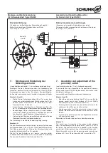
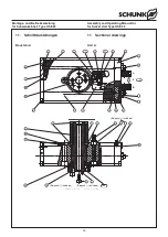
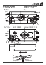
Montage- und Betriebsanleitung
für Schwenkeinheit Type OSE 22
Assembly and Operating Manual for
for Swivel Unit Type OSE 22


