


13
Montage- und Betriebsanleitung
für Schwenkeinheit Type OSE 22
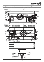
Assembly and Operating Manual for
for Swivel Unit Type OSE 22
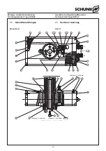
OSE C 22 - 0
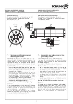
OSE C 22 - 4
Pos.
Id.-No.
Bezeichnung / Description
St. / pc.
40
9612 609 Zylinderdichtung / Cylinder seal 22 x 16 x 2.55
2
42
9612 651 Kolbenführungsband / Piston guiding band
4
46
9611 143 O-Ring / O-ring DIN 3771 NBR 70 25 x 1.50
2
51
9611 112 O-Ring / O-ring DIN 3771 NBR 70 4 x 1.5
2
56
9612 603 Dichtung / Seal GM 2000 M 8
4
58
99611 118 O-Ring / O-ring NBR 70 50 x 1.5
1
Pos.
Id.-No.
Bezeichnung / Description
St. / pc.
40
9612 609 Zylinderdichtung / Cylinder seal 22 x 16 x 2.55
2
42
9612 651 Kolbenführungsband / Piston guiding band
4
46
9611 143 O-Ring / O-ring DIN 3771 NBR 70 25 x 1.50
2
51
9611 112 O-Ring / O-ring DIN 3771 NBR 70 4 x 1.5
2
55
9611 115 O-Ring / O-ring DIN 3771 NBR 70 18 x 1
2
58
99611 118 O-Ring / O-ring NBR 70 50 x 1.5
1
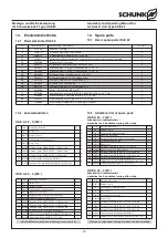
10.4 Dichtsatzlisten
10.4 Seal kit list
OSE A 22 - 0
OSE B 22 - 0
Pos.
Id.-No.
Bezeichnung / Description
St. / pc.
40
9612 609 Zylinderdichtung / Cylinder seal 22 x 16 x 2.55
2
42
9612 651 Kolbenführungsband / Piston guiding band
4
46
9611 143 O-Ring / O-ring DIN 3771 NBR 70 25 x 1.5
2
50
9611 061 O-Ring / O-ring DIN 3771 NBR 70 13 x 1.5
5
51
9611 112 O-Ring / O-ring DIN 3771 NBR 70 4 x 1.5
2
52
9611 155 O-Ring / O-ring DIN 3771 NBR 70 2.5 x 1
4
56
9612 603 Dichtung / Seal GM 2000 M 8
4
58
99611 118 O-Ring / O-ring NBR 70 50 x 1.5
1
OSE A 22 - 4
Pos.
Id.-No.
Bezeichnung / Description
St. / pc.
40
9612 609 Zylinderdichtung / Cylinder seal 22 x 16 x 2.55
4
42
9612 651 Kolbenführungsband / Piston guiding band
4
46
9611 143 O-Ring / O-ring DIN 3771 NBR 70 25 x 1.5
2
48
9611 163 O-Ring / O-ring DIN 3771 NBR 70 4 x 1
1
49
9611 054 O-Ring / O-ring DIN 3771 NBR 70 3 x 1
2
51
9611 112 O-Ring / O-ring DIN 3771 NBR 70 4 x 1.5
3
54
9611 063 O-Ring / O-ring DIN 3771 NBR 70 6 x 1
2
56
9612 603 Dichtung / Seal GM 2000 M 8
2
57
9612 604 Dichtung / Seal GM 2000 M 6
2
58
99611 118 O-Ring / O-ring NBR 70 50 x 1.5
1
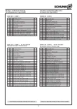
OSE C 22 - 0
Pos.
Id.-No.
Bezeichnung / Description
St. / pc.
40
9612 609 Zylinderdichtung / Cylinder seal 22 x 16 x 2.55
4
42
9612 651 Kolbenführungsband / Piston guiding band
4
46
9611 143 O-Ring / O-ring DIN 3771 NBR 70 25 x 1.5
2
48
9611 163 O-Ring / O-ring DIN 3771 NBR 70 4 x 1
1
49
9611 054 O-Ring / O-ring DIN 3771 NBR 70 3 x 1
2
50
9611 061 O-Ring / O-ring DIN 3771 NBR 70 13 x 1.5
5
51
9611 112 O-Ring / O-ring DIN 3771 NBR 70 4 x 1.5
3
52
9611 155 O-Ring / O-ring DIN 3771 NBR 70 2.5 x 1
8
54
9611 063 O-Ring / O-ring DIN 3771 NBR 70 6 x 1
2
56
9612 603 Dichtung / Seal GM 2000 M 8
2
57
9612 604 Dichtung / Seal GM 2000 M 6
2
58
99611 118 O-Ring / O-ring NBR 70 50 x 1.5
1
OSE C 22 - 4
Pos.
Id.-No.
Bezeichnung / Description
St. / pc.
40
9612 609 Zylinderdichtung / Cylinder seal 22 x 16 x 2,55
2
42
9612 651 Kolbenführungsband / Piston guiding band
4
46
9611 143 O-Ring / O-ring DIN 3771 NBR 70 25 x 1,5
2
50
9611 061 O-Ring / O-ring DIN 3771 NBR 70 13 x 1,5
5
51
9611 112 O-Ring / O-ring DIN 3771 NBR 70 4 x 1,5
2
52
9611 155 O-Ring / O-ring DIN 3771 NBR 70 2,5 x 1
4
55
9611 115 O-Ring / O-ring DIN 3771 NBR 70 18 x 1
2
58
99611 118 O-Ring / O-ring NBR 70 50 x 1.5
1
OSE B 22 - 4
Verschleißteile, empfohlen bei Wartung auszutauschen
Wear parts; replacement during maintenance recommended
Pos.
Id.-No.
Bezeichnung / Description
St. / pc.
20
5506 286
Zentrierbuchse / Centering bushing Ø 12 x 10
2
51
9611 112
O-Ring / O-ring DIN 3771 NBR 4.00 x 1.5
3
71
9660 013
Schrauben / Screws DIN EN ISO 4762 / 12.9 M 5.0 x 20 mm
2
77
9669 053
Passschraube UPS / Adjustment screw UPS 6 M 5.0 x 16 mm
2
80
9659 005
Verschlussschraube / Sealing screw M 5
3
Pos.
Id.-No.
Bezeichnung / Description
St. / pc.
20
5506 286
Zentrierbuchse / Centering bushing Ø 12 x 10
2
51
9611 112
O-Ring / O-ring DIN 3771 NBR 4.00 x 1.5
3
52
9611 155
O-Ring / O-ring DIN 3771 NBR 2.50 x 1.0
4
71
9660 013
Schrauben / Screws DIN EN ISO 4762 / 12.9 M 5.0 x 20 mm
2
77
9669 053
Passschraube UPS / Adjustment screw UPS 6 M 5.0 x 16 mm
2
80
9659 005
Verschlussschraube / Sealing screw M 5
3
81
9670 501
Gewindestift / Set screw DIN EN ISO 4026 / A2 M 5.0 x 5 mm Tufloc
3


