


5
Montage- und Betriebsanleitung
für Schwenkeinheit Type OSE 22
Assembly and Operating Manual for
for Swivel Unit Type OSE 22
3.
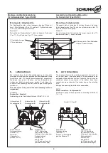
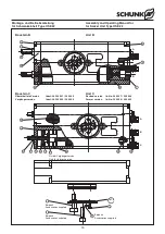
Lieferumfang
(Positionsnummern, siehe Ersatzteilstücklisten Kapitel 10, sowie
Schnittdarstellungen Kapitel 11)
–
Schwenkeinheit
(ohne Adapterplatte und ohne Näherungsschalter)
–
2 O-Ringe für bodenseitigen Direktanschluss
(Baustein C: 3 Stück) (Pos. 51)
–
2 Pass-Schrauben (Pos. 76) oder (Pos. 77)
–
2 Zentrierbuchsen (Pos. 20)
–
2 Drosselrückschlagventile (Baustein C: 3 Stück) (Pos. 97)
und (Pos. 98)
–
1 Halterung (Pos. 21) incl. 2 Näherungsschalterhülsen (Pos.
32) und Näherungsschalterhalter (Pos. 22)
–
2 Schaltnocken (Baustein C: 3 Stück) (Pos. 23)
–
1 Steckschlüssel (bei Baustein B) (Pos. 39)
Einheiten mit Luftdurchführung
–
4 O-Ringe (Pos. 52)
ZUBEHÖR:
(bei separater Bestellung, siehe Katalog)
–
Näherungsschalter
–
Sicherheitsventil
4.
Technische Daten
Die technischen Daten entnehmen Sie bitte dem aktuellen Katalog.
HINWEIS:
Bitte prüfen Sie, ob Ihr Einsatzfall anhand des Berechnungs-
programms
Auswahlsystem für SCHUNK Schwenkeinheiten
geprüft wurde.
Falls nicht, kann für die Stoßdämpfer keine Gewährleistung über-
nommen werden.
Der von den Einheiten ausgehende Luftschall ist
≤
70 dB (A).
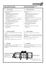
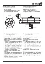
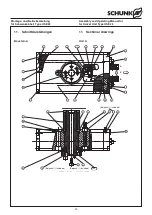
5.
Montage
Die Schwenkeinheit kann an den 2 Innengewinden oder mit
Schrauben M6 x 40 (Pos. 69) befestigt werden.
Zur Zentrierung verwenden Sie die Zentrierhülsen (Pos. 20) aus
dem Beipack.
Durchgangsloch für
Schrauben (Pos. 69):
M6 x 40 DIN EN ISO 4762
Through-hole for screws
(item 69)
M6 x 40 DIN EN ISO 4762
Innengewinde: M8
Internal thread: M8
Zentrierhülse(Pos. 20): Ø 12
f7
Centering sleeve (item 20): Ø 12
f7
3.
Scope of Delivery
(For item-no. see spare part lists chapter 10, as well as the
sectional view chapter 11).
–
Swivel unit
(without adaptor plate and without proxi-mity switch).
–
2 O-rings for direct connection at the bottom
(module C: 3 pieces) (item 51)
–
2 Dowel screws (item 76) or (item 77)
–
2 Centering bushings (item 20)
–
2 Double check valves (module C: 3 pieces) (item 97) and
(item 98)
–
1 Bracket (item 21) incl. 2 sleeves for proximity switches
(item 32), bracket for proximity switch (item 22)
–
2 Control cams (module C: 3 pieces) (item 23)
–
1 Actuation key (for module B) (item 39)
Units with an air through feeding system
–
4 O-rings (item 52)
ACCESSORIES:
(on separate order, see catalogue)
–
Proximity switch
–
Safety valve
4.
Technical Data
For technical data, please refer to the current catalogue.
NOTE:
Please make sure that your case of application was checked with
our calculation programme
“Selection System for SCHUNK
Swivel Units”
.
If not, we can’t give warranty for the shock absorbers.
The airborne noise emitted is
≤
70 dB (A).
5.
Assembly
The swivel unit can be fastened with 2 socket head cap screws
M6 x 40 (item 69) or 2 internal threads.
To locate swivel unit use two centering sleeves (item 20) from the
accessories supplied.


