background image


Assembly 


04.01|MPG-plus |en 

21 


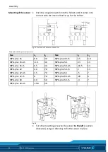
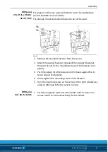
To use the inductive sensor, the gripper has to be retrofitted with a 
special mounting kit. This mounting kit is available from SCHUNK for 
the models below.  


4

3

2

1

2

3


Fig. 10 


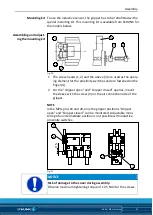
1  The screw heads (1, 2) and the sleeve (3) are used as the query-

ing element for the proximity switches and are fastened on the 
finger (4). 

2  For the "Gripper open" and "Gripper closed" queries, mount 

the sleeve with the screw (2) on the air connection side of the 
gripper. 


NOTE 

In the MPG-plus 16 and 20, only the gripper positions "Gripper 

open" and "Gripper closed" can be monitored. Adjustable moni-

toring of an intermediate position is not possible with inductive 

proximity switches.  

5

6

2

7


Fig. 11 


NOTICE 

Risk of damage to the cover during assembly. 

Observe maximum tightening torque of 12,5 Ncm for the screws. 


Mounting kit 

Assembling and adjust-

ing the mounting kit 

Summary of Contents for MPG-plus

Page 1: ...Translation of the original manual 2 finger parallel gripper MPG plus Assembly and operating manual Superior Clamping and Gripping ...

Page 2: ... 18 02 2015 en SCHUNK GmbH Co KG All rights reserved Dear customer congratulations on choosing a SCHUNK product By choosing SCHUNK you have opted for the highest precision top quality and best service You are going to increase the process reliability of your production and achieve best machining results to the customer s complete satisfaction SCHUNK products are inspiring Our detailed assembly and...

Page 3: ...ssories 12 5 1 Sensors 12 6 Technical data 12 7 Assembly 13 7 1 Mechanical connection 13 7 2 Air connections 15 7 3 Sensors 16 7 3 1 Inductive proximity switch IN 3 S 16 7 3 2 Inductive proximity switch IN 5 S 17 7 3 3 Inductive proximity switch IN40 20 7 3 4 MMS P programmable magnetic switch 22 7 3 5 Analog magnet sensor MMS A 27 7 3 6 MMS PI2 programmable magnetic switch 28 7 3 7 FPS flexible p...

Page 4: ... 3 Lubricants Lubrication points 35 10 Assembly drawings 36 10 1 Assembly of the variant without gripping force maintenance 36 10 2 Assembly of the variant with O D gripping 37 10 3 Assembly of the variant with I D gripping 38 11 Sealing kit 39 12 Accessories kit 39 13 Translation of original declaration of incorporation 40 ...

Page 5: ...ter Basic safety notes Warnings To make risks clear the following signal words and symbols are used for safety notes DANGER Danger for persons Non compliance will inevitably cause irreversible injury or death WARNING Dangers for persons Ignoring a safety note like this can lead to irreversible injury and even death CAUTION Dangers for persons Non observance can cause minor injuries NOTICE Material...

Page 6: ... with gripping force maintenance O D gripping MPG plus with gripping force maintenance I D gripping MPG plus High temperature version HT Applicable documents General terms of business Catalog data sheet of the purchased product Assembly and Operating manuals of the accessories The documents listed here can be downloaded on our homepage www schunk com 1 2 1 3 ...

Page 7: ...s intended it is also essential to observe the technical data and installation and operation notes in this manual and to comply with the maintenance intervals Not intended use Use which is not specified as an intended use is for instance when the product is for example used as a pressing tool stamping tool lifting tool guide for tools cutting tool tensioning mean boring tool Environmental and oper...

Page 8: ...on The assembly initial commissioning maintenance and repair of the product may be performed only by trained specialist person nel Every person called upon by the operator to work on the product must have read and understood the complete assembly and operating manual especially the chapter Basic safety notes 2 Page 7 This applies particularly to personnel only used oc casionally such as maintenanc...

Page 9: ...ions and additions outside the danger zone Secure the product during all operations against uncontrolled activation Take a precautionary approach by maintenance and disassembly Only specially trained staff should disassemble the product WARNING Risk of injury due to squeezing and bumping during movement of the gripper jaws and breaking or loosening of the gripper fingers WARNING Risk of injury fro...

Page 10: ...ripping force maintenance Secure the end positions of the product with SCHUNK SDV P pressure maintenance valves WARNING Risk of injury due to residual energy in the gripper because of gripping force maintenance by springs WARNING Risk of injury due to spring forces While disassembling uncontrollable moves of parts of the gripper possible For modules which clamp with spring tension or gripping forc...

Page 11: ... in 1 shift operation Observe the mandatory maintenance and lubrication intervals Observe the environmental and operating conditions Parts touching the work piece and wear parts are not part of the warranty If necessary check the application with the calculation program for gripping modules SSG Scope of delivery The scope of delivery includes 2 finger parallel gripper MPG plus in the ordered model...

Page 12: ...er variants X X X Exact type designation of the compatible sensors see catalog If you require information on sensor operation contact your SCHUNK contact person or download information from our homepage www schunk com For mounting the sensors mounting kits are partly necessary Technical data Pressure medium Compressed air compressed air quality according to ISO 8573 1 7 4 4 Nominal working pressur...

Page 13: ... Requirements for levelness of the bolting surface Dimensions in mm Diameter Permissible unevenness 100 0 02 100 0 05 The module can be mounted from the front from the rear or on the side Fig 1 Assembly options 1 Mounting from the rear 4 Centering sleeves 2 Side mounting 5 Thread in top jaws 3 Side mounting 6 Fixing bores for cylindrical pin 7 7 1 Check the evenness of the bolting surface Mounting...

Page 14: ...erve maximum tightening torques of the following table If possible hold hold up to the top jaws during assembly so that the forces on the guide are not too large mounting of the top jaws Designation MPG plus 16 20 25 32 40 50 64 Thread in top jaws M3 M4 M4 M5 M5 M6 M8 Maximum tightening torque for the mounting screws Nm 1 2 3 1 3 1 6 1 6 1 10 25 mounting of the top jaws ...

Page 15: ...plement sufficient reduction and or damping Observe the diagrams and information in the catalog data sheet NOTICE Observe the requirements for the air supply 6 Page 12 Fig 2 Air connections 1 Main connections Hose connection A open B closed 2 Hose free direct connection at the base a open b closed Open only the air connections that are needed Close unused main air connections using the screw plugs...

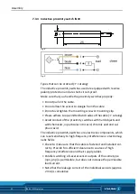
Page 16: ...oximity switch IN 3 S Fig 3 Fig 4 Types available for order see catalog The inductive proximity switches used are equipped with reverse polarity protection and are short circuit proof Make sure that you handle the proximity switches properly Do not pull on the cable Do not allow the sensor to dangle from the cable Do not overtighten the mounting screw or mounting clip Please adhere to a permitted ...

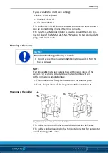
Page 17: ... switching of several sensor outputs of the same type npn pnp is permissible but does not increase the permissible load current Note that the leakage current of the individual sensors approx 2 mA is cumulative To use the inductive sensor the gripper has to be retrofitted with a special mounting kit This mounting kit is available from SCHUNK for the models below Follow the instructions for proper u...

Page 18: ...ilable from SCHUNK for the models below Fig 7 MPG plus 25 64 1 Remove the name plate 2 Fasten the holder 1 3 Remove the screws 2 and cover 3 4 MPG plus 25 40 The switching lug 4 is fastened directly to the base jaw 5 MPG plus 50 64 The switching lugs 6 and 7 with the covers 3 are fastened directly to the base jaws 5 5 Insert both proximity switches into the holder 1 with the switch areas in the di...

Page 19: ...ches and then further forward another 0 5 mm in the same direction 3 Tighten the screw to fix the switching point 4 Open the gripper and close it again in order to test the function Part gripped 1 Move the gripper into the Open position upon request Gripper open and Part gripped or in the Closed position upon request Gripper closed and Part gripped 2 Push forward the free proximity switch in the s...

Page 20: ... Avoid contact of the proximity switches with hard objects and with chemicals in particular nitric acid chromic acid and sul phuric acid The inductive proximity switches are electronic components which can react sensitively to high frequency interference or electromag netic fields Check to make sure that the cable is fastened and installed cor rectly Provide for sufficient clearance to sources of ...

Page 21: ...e finger 4 2 For the Gripper open and Gripper closed queries mount the sleeve with the screw 2 on the air connection side of the gripper NOTE In the MPG plus 16 and 20 only the gripper positions Gripper open and Gripper closed can be monitored Adjustable moni toring of an intermediate position is not possible with inductive proximity switches 5 6 2 7 Fig 11 NOTICE Risk of damage to the cover durin...

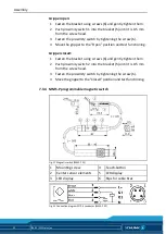
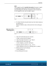
Page 22: ...ipper closed 1 Fasten the bracket using screws 6 and gently tighten them 2 Push proximity switch 2 into the bracket 5 until it is 0 5 mm from the screw head 3 Fasten the proximity switch by tightening the screw 6 4 Move the gripper to the Closed position and test functioning MMS P programmable magnetic switch Fig 12 Magnetic switch MMS P 22 1 Mounting screw 4 Teach button 2 Center sensor elements ...

Page 23: ...uring assembly Do not exceed the maximum tightening torque of 10 Ncm for the set screws NOTE Ferromagnetic material changes the switching positions of the sensor For example Adapter plate made of ordinary steel At ferromagnetic adapter plates The module must firstly be mounted on the adapter plate Then the positions of the magnetic switch have to be set Fig 14 Vertical horizontal attachment of the...

Page 24: ... 25 6 8 3 0 MPG plus 40 IS 1 5 5 0 MPG plus 25 AS 6 0 3 0 MPG plus 50 2 3 13 MPG plus 25 IS 6 5 3 0 MPG plus 50 AS 16 5 13 MPG plus 32 4 0 7 0 MPG plus 50 IS 2 13 MPG plus 32 AS 1 5 7 0 MPG plus 64 5 7 MPG plus 32 IS 0 7 0 MPG plus 64 AS 20 6 MPG plus 40 3 0 5 0 MPG plus 64 IS 4 7 MPG plus 40 AS 19 0 5 0 Fig 16 1 Turn the mounting screw on the sensor to the left counter clockwise using an Allen ke...

Page 25: ...cs have to be fixed in place us ing cable ties 7 There are ribs 6 in place on the electronics for mounting pur poses Fig 18 1 Press the Teach button 4 for 2 seconds After 2 seconds LED 1 3 flashes 2 Move the gripper to position 1 e g Open 3 Briefly press the Teach button 4 LED 1 3 lights up and LED 2 5 flashes 4 Move the gripper to position 2 e g 2mm LED 1 3 goes out as soon as switching point 1 i...

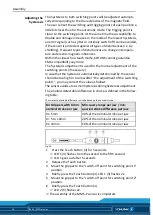
Page 26: ...omatically determined by the sensor should be too high or too low after the adjustment of the switching points you may correct the value as follows The sensor avoids a too small hysteresis during hysteresis adjustment The smallest detectable difference in stroke is defined in the follow ing table The smallest detectable difference in stroke based on the nominal stroke For Grippers with X mm nomina...

Page 27: ...w on the sensor to the right clockwise using an Allen key to fix the sensor in place For the gripper in this size a special fastener in the scope of deli very has to be used The already mounted standard fastener can not be used Fig 20 1 Remove the standard fastener from the sensor 2 Mount the special fastener instead of the standard fastener However do not fix the mounting screws of the fastener c...

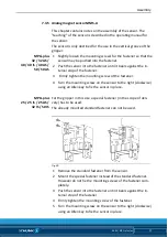
Page 28: ... in place MMS PI2 programmable magnetic switch This chapter contains notes on the assembly of the sensor The teaching of the sensor is described in the operating manual for the sensor The sensor is only destined for the use in the vertical groove of the gripper 1 Slightly loosen the mounting screws for the fastener so that the sensor may be pushed into the fastener 2 Push the sensor into the faste...

Page 29: ...r However do not fix the mounting screws of the fastener com pletely 3 Push the sensor into the fastener until it bears against the in ternal stop of the fastener 4 Firmly tighten the mounting screw of the fastener 5 Turn the mounting screw on the sensor to the right clockwise using an Allen key to fix the sensor in place 1 Push the magnetic switch into the holder until it comes into contact with ...

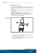
Page 30: ...o the gripper To install the FPS S13 flexible position sensor onto the MPG plus 40 50 64gripper a mounting kit must be mounted on the gripper This mounting kit can be ordered from SCHUNK Types that can be ordered see catalog 3 4 1 2 Fig 22 FPS version MPG plus 20 32 1 Position the active sensor area circular elevation 1 in the re cess provided for it in the housing 2 2 Fasten the FPS S13 position ...

Page 31: ...S13 position sensor to the bracket 1 using the two screws 3 max tightening torque 1 Ncm 4 5 Fig 24 3 Fasten the control cam 4 to the finger using the screw 5 Magnets have to point toward the sensor area of the FPS S13 position sensor The adjustment of the sensor is described in the operating ma nual for the sensor Mounting of the mounting kit ...
Page 32: ...valve Component is broken e g through over loading Replace component or send the module with a repair order to SCHUNK Ensure that the module was only used within its defined application parameters If necessary check the application with the calculation program for gripping modules SSG The module does not travel through the entire stroke Possible cause Corrective action Dirt deposits between the co...

Page 33: ...15 Module does not achieve the opening and closing times Possible cause Corrective action Compressed air lines are not installed optimally If present Open the flow control couplings on the module to the maximum that the movement of the jaws occurs without bouncing and hitting Check compressed air lines Inner diameter of the compressed air lines are sufficiently large relative to the compressed air...

Page 34: ... only use SCHUNK original spares Replacement of housing and base jaws The base jaws and the guides in the housing are matched to each other To have these parts replaced send the complete module along with a repair order to SCHUNK Maintenance of module with gripping force maintenance I D gripping I D and A D gripping A D The pistons have to be aligned using an assembly device There fore we recommen...

Page 35: ...cycles 15 5 4 3 Lubricants Lubrication points We recommend the lubricants listed During maintenance treat all greased areas with lubricant Thinly apply lubricant with a lint free cloth Lubricant point Lubricant Metallic sliding surfaces microGLEIT GP 360 All seals Renolit HLT 2 Bores on the piston Renolit HLT 2 In addition to the described maintenance the guides of the gripper can be re lubricated...

Page 36: ...ations are possible depending on size and variant Assembly of the variant without gripping force maintenance Fig 25 Assembly of the variant without gripping force maintenance Wearing part replace during maintenance Included in the seal kit Seal kit can only be ordered com pletely Positions are adapted to each other and can not be re placed by the customer 10 10 1 ...

Page 37: ...pring forces The lid is under spring tension Carefully disassemble the module Fig 26 Assembly of the variant with O D gripping Wearing part replace during maintenance Included in the seal kit Seal kit can only be ordered com pletely Positions are adapted to each other and can not be re placed by the customer 10 2 ...

Page 38: ...pring forces The lid is under spring tension Carefully disassemble the module Fig 27 Assembly of the variant with I D gripping Wearing part replace during maintenance Included in the seal kit Seal kit can only be ordered com pletely Positions are adapted to each other and can not be re placed by the customer 10 3 ...

Page 39: ...G plus 64 5520769 Contents of the seal kit 10 Page 36 Accessories kit Content of the accessories pack 2 x Centering sleeves for mounting 2 x O ring for hose free direct connection 2 x Screw plug for hose connection 2 x Grub screw for MPG plus 16 25 ID No of the accessory pack Accessory pack for ID number MPG plus 16 5522565 MPG plus 20 5522566 MPG plus 25 5510172 MPG plus 32 40 5510173 MPG plus 50...

Page 40: ...ger parallel gripper MPG plus pneumatic ID number 0305481 0305543 39305481 39305543 The incomplete machine may not be put into operation until conformity of the machine into which the incomplete machine is to be installed with the provisions of the Machinery Directive 2006 42 EC is confirmed Applied harmonized standards especially EN ISO 12100 2011 03 Safety of machinery General principles for des...

Reviews: