


Assembly
24
04.01|MPG-plus |en
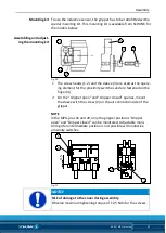
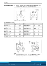
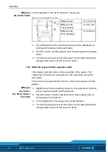
1 Push the magnetic switch into the holder until it comes into
contact with the internal back stop for the holder.
Fig. 15
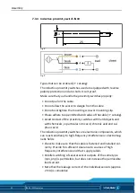
Protrusion of the mounted sensor
Dimensions of the protrusion in mm
Size
L
1
L
2
Size
L
1
L
2
MPG-plus 25
6.8
3.0
MPG-plus 40-IS
1.5
5.0
MPG-plus 25-AS
-6.0
3.0
MPG-plus 50
2.3
13
MPG-plus 25-IS
6.5
3.0
MPG-plus 50-AS
-16.5
13
MPG-plus 32
4.0
7.0
MPG-plus 50-IS
2
13
MPG-plus 32-AS
1.5
7.0
MPG-plus 64
-5
7
MPG-plus 32-IS
0
7.0
MPG-plus 64-AS
-20
6
MPG-plus 40
3.0
5.0
MPG-plus 64-IS
-4
7
MPG-plus 40-AS
-19.0
5.0
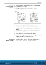
Fig. 16
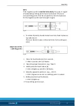
1 Turn the mounting screw on the sensor
to the left
(counter-
clockwise) using an Allen key to fix the sensor in place.
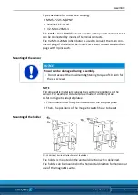
Mounting of the sensor


