background image

14. Appendix

Reference Manual |Edition 4.0 (10-2013) |EcoCut 3300

97|108

MICROLUBE GBU-Y 131

Conforms to Regulation (EC) No. 1907/2006 (REACH), Annex II - United Kingdom (UK)

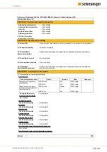
SECTION 9: Physical and chemical properties

Auto-ignition temperature

Not available.

Not available.

Viscosity

Not available.

Explosive properties

:

:

:

Not available.

Oxidising properties

:

9.2 Other information

Decomposition temperature

:

Not available.

No additional information.

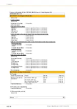
10.6 Hazardous
decomposition products

10.4 Conditions to avoid

No specific data.

Under normal conditions of storage and use, hazardous decomposition products

should not be produced.

The product is stable.

10.2 Chemical stability

No specific data.

:

:

:

10.5 Incompatible materials

:

10.3 Possibility of
hazardous reactions

:

Under normal conditions of storage and use, hazardous reactions will not occur.

SECTION 10: Stability and reactivity

10.1 Reactivity

:

No specific test data related to reactivity available for this product or its ingredients.

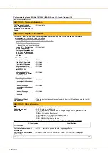
Acute toxicity

Residual oils (petroleum),

hydrotreated

LD50 Dermal

Rat

>5000 mg/kg

-

LD50 Oral

Rat

>5000 mg/kg

-

Benzenamine, N-phenyl-,

reaction products with 2,4,4-

trimethylpentene

LD50 Dermal

Rabbit

>2000 mg/kg

-

LD50 Oral

Rat

>5000 mg/kg

-

Product/ingredient name

Result

Species

Dose

Exposure

Conclusion/Summary

:

Not available.

Carcinogenicity

Conclusion/Summary

:

Not available.

Mutagenicity

Conclusion/Summary

:

Not available.

Teratogenicity

Conclusion/Summary

:

Not available.

Reproductive toxicity

Conclusion/Summary

:

Not available.

Irritation/Corrosion

Conclusion/Summary

:

Not available.

Sensitiser

Conclusion/Summary

:

Not available.

SECTION 11: Toxicological information

11.1 Information on toxicological effects

Acute toxicity estimates

Not available.

Specific target organ toxicity (single exposure)

Specific target organ toxicity (repeated exposure)

Not available.

Version

:

6/10

1

Summary of Contents for EcoCut 3300

Page 1: ...EcoCut 3300 Automatic Cutting Machine Reference Manual Software Version 1 1x Edition 4 0 10 2013...

Page 2: ...4 42477 Radevormwald Germany P 49 0 21 959 29 0 F 49 0 21 959 29 105 info schleuniger de www schleuniger com Schleuniger Inc 87 Colin Drive Manchester NH 03103 USA P 1 603 668 81 17 F 1 603 668 81 19...

Page 3: ...Trademarks 11 1 9 SPARE PARTS 12 2 SAFETY 13 2 1 WARNING NOTICES 13 2 2 GENERAL SAFETY NOTES 13 2 3 SOURCES OF DANGER RISKS 13 2 4 INTENDED USAGE OF PRODUCT 14 2 5 SAFETY SYMBOLS 14 2 5 1 Safety symbo...

Page 4: ...24 5 3 REAR CONNECTORS 24 5 3 1 Postfeed interface PPI option 25 5 3 2 RS 232 interface 25 5 3 3 HS PF HotStamp Prefeeder interface 25 5 3 4 Pedal connector 26 5 3 5 Rating plate 26 5 3 6 Power connec...

Page 5: ...MAIN MENU 39 8 4 WIRE SCREENS 39 8 4 1 Wire data 1 40 8 4 2 Wire data 2 40 8 4 3 Wire marking 41 8 4 4 Wire stacker PPI option 42 8 4 5 Cable coiler PPI option 42 8 5 FILE MENU 42 8 5 1 New 43 8 5 2 L...

Page 6: ...1 3 CLASSIFICATION 59 11 3 1 Access rights 59 11 4 MAINTENANCE SCHEDULE 59 11 4 1 General 60 11 4 2 Maintenance chart 60 11 5 CIRCUIT DIAGRAMS DRAWINGS SPARE PART LISTS 60 11 6 SPECIFICATION OF SPARE...

Page 7: ...talling Iguana 77 14 1 2 Downloading upgrade file 77 14 1 3 Upgrade procedure 78 14 2 CONNECTOR HS PF 79 14 2 1 For use with a PreFeeder 79 14 2 2 For use with a HotStamp 80 14 3 PRE POSTFEED INTERFAC...

Page 8: ...Table of contents 8 108 Reference Manual Edition 4 0 10 2013 EcoCut 3300...

Page 9: ...s for the application field valid local accident preven tion regulations and general safety regulations must be complied If the product changes hands the Operator s Handbook must be supplied to the ne...

Page 10: ...o the operating personnel at all times Keep the Operator s Handbook in such a way that it will not become damaged so that the contents will remain clearly legible beyond the expected lifespan of the p...

Page 11: ...egister 2 of the ring binder 1 6 LIMITATION OF LIABILITY The content of these operating instructions was put together taking into consideration the current stand ards and guidelines according to the s...

Page 12: ...S Always order original spare parts from your local Schleuniger distributor Any modifications in design or function of the spare parts in terms of ongoing product improvement are subject to change wit...

Page 13: ...if not avoided can result in damage to property 2 2 GENERAL SAFETY NOTES The product must only be operated when in good working order and condition It must be checked for intactness prior to the start...

Page 14: ...g falling slipping due to connection cables wire residue and air hoses lying around Risk of increased noise levels while working with multiple machines in the room Arrange for noise control measures W...

Page 15: ...to younger person WARNING Risk of injury if operated by unqualified personnel Improper handling of the machine may lead to serious injury to personnel and damage to the property 2 7 1 Personnel classi...

Page 16: ...parts Protects from getting caught up in moving machine parts 2 8 3 Safety shoes To protect from heavy falling objects or reels 2 8 4 Snood type cap or safety cover To protect long hair from getting c...

Page 17: ...er must be carried out by qualified personnel 3 1 TRANSPORT INSPECTION Check the goods immediately after receiving for completeness and loss during shipment For loss on the packaging during shipment p...

Page 18: ...load dislocation During transportation in a craft the product may slip off and cause serious material damage Even the craft may start skidding which could result in an accident with incalculable cons...

Page 19: ...Any modifications in design or function in terms of ongoing product improvement are subject to change without prior notification 4 1 DIMENSIONS WEIGHT A B C Fig 1 Dimensions Description Value Unit We...

Page 20: ...humidity maximum 90 20 C 50 40 C Storage and transport temperature 25 to 55 C Interfaces Prefeeders and wire marker devices RS 232 Optional Pre Postfeed interface for synchron ized peripheral devices...

Page 21: ...e rating plate The rating plate is situated on the rear of the machine and contains the following information Schleuniger AG Model EcoCut 3300 Made in Switzerland Serial No Power rating Bierigutstrass...

Page 22: ...4 Product specifications 22 108 Reference Manual Edition 4 0 10 2013 EcoCut 3300...

Page 23: ...ass Fiber Optic GOF cable The automatic cutting machine provides precise reliable results The EcoCut 3300 may be used as a stand alone machine as well as in combination with various peripheral devices...

Page 24: ...this lever the ejection chute is aligned in height to the post processing device cable coiler wire stacker 5 2 5 Wire end switch The wire end switch checks whether a wire is inserted or the processed...

Page 25: ...terface PPI option This optional interface includes the following ports for synchronized peripheral devices CableCoiler 500 CableCoiler 1300 Coilers and stackers from third party vendors with device s...

Page 26: ...a PreFeeder Page 79 listed Schleuniger peripheral devices The Prefeed operation may be monitored by the EcoCut 3300 see also chapter 14 2 1 1 Input PFREADY Pin 10 11 Page 80 5 3 4 Pedal connector The...

Page 27: ...abels must be replaced immediately For further information see chapter 5 Product description Page 23 5 4 2 Danger zones operating area Danger zones on this machine are eliminated by design measures an...

Page 28: ...on the mains socket Touching electric components can cause injury to the operator personnel Unintentional operation of pressurized components or uninten tionally escaping compressed air can cause inju...

Page 29: ...the user The following security relevant points have to be mentioned specially This is a free standing product The machine must only be operated in a dust free and dry area The electric connection mus...

Page 30: ...enu language measuring unit with ENTER 4 Back to the main menu with 2 MENU 6 3 3 Connecting compressed air option NOTICE Caution property damage The supplied operating pressure to the machine must not...

Page 31: ...Product description Page 23 See also chapter 5 4 Dangerous zones on the machine Page 27 7 2 SWITCHING ON 1 Turn on the main switch on the rear of the machine see 5 3 7 Main power switch Page 26 2 Wait...

Page 32: ...everal wires option 1 Mount the multiple wire guide 1 2 Load the wire see above 1 7 4 2 Producing a wire 1 Load a single wire or multiple wires see above 2 Select the desired wire program see chapter...

Page 33: ...e wire guide 1 Switch off and unplug the machine from the mains supply 2 Turn the machine to the side 3 Loosen the two screws 1 4 Pull out the front sheet in direction of arrow 1 2 5 Turn the locking...

Page 34: ...s are set up so that the collar guide snaps into the groove 9 Mount the front sheet 2 10 Connect the machine to the mains and switch it on 7 6 WORK TO BE DONE AFTER OPERATION 7 6 1 General maintenance...

Page 35: ...keyboard and display 1 Display 4 Navigation keys 2 Production keys 5 Entry keys numeric keypad 3 Function keys 8 1 1 Display Header line Main area Header line The following display is shown Product na...

Page 36: ...dialog boxes this key has the function OK Define selection Allows for an additional selection within the dialog boxes instead of OK and CANCEL Serves as an additional special function key Next This ke...

Page 37: ...s In addition the leading sign with the plus minus key and upper lower case with characters can be switched Decimal point Enter Confirms an entry and jumps to the next input field 8 2 GENERAL Below th...

Page 38: ...anual Edition 4 0 10 2013 EcoCut 3300 8 2 1 Menu structure The software of the EcoCut 3300 is structured in a main menu with 5 sub menus 8 2 2 Input area There are two types of input areas which make...

Page 39: ...put field was changed unintentionally the former value can be reset with ESC as long as that field was not exit 8 2 3 Entry fields There are three types of input fields Toggle fields Numeric fields Te...

Page 40: ...ey to enter the following screens 8 4 2 Wire data 2 1 X Here the speed and the ramp acceleration with which the wire shall be transported is determined Speed These settings change the feed speed of th...

Page 41: ...to the cor rection field the measured wire length is reset to 0 and marked with an x at the length line on the screen Wire data 1 8 4 3 Wire marking In this screen the wire marker data is determined T...

Page 42: ...duration of the stacking Wait ms The EcoCut 3300 waits for the entered time until the WS 500 1000 was moving to its home position Sub sequently the production continuous 8 4 5 Cable coiler PPI option...

Page 43: ...ing only appears if the present wire is different from the saved one Once the message is confirmed with OK the screen Load pops up Procedure In the list in the upper area of the screen the name of the...

Page 44: ...eted 8 5 3 Save 2 3 With the menu Save the loaded and edited wire can be saved If a new unsaved wire has to be saved by means of Save the user is automatically guided to the Save as screen 8 5 4 Save...

Page 45: ...of a wire marker device the wire feeding on the EcoCut 3300 is interrupted through the Combi input until the marking procedure is completed see chapter 9 Operation using a marking device Page 53 Duri...

Page 46: ...e an error mes sage will appear The duration until an error message appears is called Timeout and can be set up Configuration Wire stacker PPI option 3 1 X X In this screen all parameters for the wire...

Page 47: ...er 3 2 In this screen the language and the measuring unit is set For this see chapter 6 3 2 Setting the measuring unit and the menu language Page 30 Available language packets Standard East English De...

Page 48: ...ire end switch Screen 4 2 1 The menu item Screen inverts the screen This way the display can be checked for pixel errors Keyboard 4 2 2 Here the functioning of the keyboard is tested There fore press...

Page 49: ...ioning of a connected prefeeder is tes ted For this follow the instructions on the screen Pedal 4 3 2 Here the functioning of a connected pedal is tested Activating or deactivating the pedal triggers...

Page 50: ...test takes about 6 seconds The single red LED on the interface test print glows The pair of LED on Postfeed flashes alternately red and green OK The relays on the test prints click hearable Error cod...

Page 51: ...vated deac tivated and the access rights are determined blocked 8 8 1 User level selection 5 1 In this mode the desired user level can be activated If this screen is left with and the password is swit...

Page 52: ...2 All rights except Configuration change user Configuration change machine Change diagnostics Produce no pass word All rights except Change configuration only turning devices on and off is allowed Exe...

Page 53: ...d Y axis 2 Plug the connecting cable into the interface HS PF If a Schleuniger HotStamp device is used the connection cable is enclosed 3 The distance 1 from the cutting axis blades of the EcoCut 3300...

Page 54: ...vice 54 108 Reference Manual Edition 4 0 10 2013 EcoCut 3300 4 Press CUT to eject the marked wire 5 Measure the distance from wire beginning to the right edge of the marking 6 Enter the distance in th...

Page 55: ...1 1 Safety instructions General Safety appliances must not be deactivated or removed inadvertently If a fault condition occurs always check first if the line power is switched on and then perform a di...

Page 56: ...No pedal detected Appears on diagnostic if a pedal is being tested but none is connected 12 RAM corrupted Machine stopped Replace hardware The internal memory changed unintended This indicates an err...

Page 57: ...be lost Really want to delete whole memory There is an option to delete the complete memory This warning reminds you of it 105 No more wire The wire end switch is activated during production Wire stil...

Page 58: ...3300 Warning Text Explanation 999 Delete warn again Delete without warning message Do not delete Appears with deletion of wire data 10 6 ACTIONS AFTER SOLVING ERRORS To check the correct functioning o...

Page 59: ...ustomer in case of technical problems with the machine to contact the local distributor first see http www schleuniger com 11 2 2 Behavior in case of an error If problems occur which cannot be solved...

Page 60: ...following chart Component Activity Interval Reference Page Time con sumed Min Housing clean weekly 61 5 Processing area clean weekly 61 5 Blade Check clean every 6 month 66 5 Feed rollers Check clean...

Page 61: ...4 Clean the blades and the feed rollers as nee ded with the brush 11 8 SETTINGS The machine was calibrated in the factory to your needs After a blade replacement the replacement of mechanical or elect...

Page 62: ...ition 6 Move the pin 2 to the middle of the cutout 7 Tighten the three screws 1 on the lower blade slightly The lower blade now is press ed against the upper one 8 Move the upper blade upwards and tig...

Page 63: ...he key 3 10 Press 3 Product name this screen contains all the machine settings for the EcoCut 3300 Display Contrast Adjusts the contrast level of the display Blade resolution Amount of pulses cutter h...

Page 64: ...he screen Back to factory defaults 12 SINGLE 13 DEL 14 ENTER 15 3 f 16 2 a 17 2 c 18 8 t 19 6 o 20 7 r 21 9 y 22 OK 23 The machine restarts in the native state 11 9 MAINTENANCE REPAIR WORK 11 9 1 Gene...

Page 65: ...pulsory follow the separate description if not stated in this Manual Before disassembly a component we recommend to make a drawing or to take a picture of the part This is helpful especially if the r...

Page 66: ...ich can cause serious injury if not handled properly during the blade change procedure 1 Remove the right cover sheet by loosening the four screws 1 Caution If an optional air jet unit has been instal...

Page 67: ...rub off the lower blade 8 and mount it together with the wedge 10 Tighten the screws very slightly so that the wedge can still be moved 11 With the pin 10 push the wedge completely to the left 12 Rub...

Page 68: ...ove the motors and the motor holders Notice Replace the complete cutter motor includ ing motor holder and pulley 7 Loosen the four screws and detach the trans port motor with pulley from the motor hol...

Page 69: ...k to its normal position 6 Loosen the nut on the tension pulley 4 and release it 7 Release both motor holders 8 Remove the cutting belt and both transport belts 4 9 Mount the new belt 5 of the transpo...

Page 70: ...wer 1 and data cable 2 of the cutter motor 2 1 3 Turn the machine to the side of the wire entry Place on a soft pad 4 Remove both screws of the cutter motor 3 5 Remove the cutter motor 3 6 Put the mac...

Page 71: ...h the bearing out in the direction of the arrow 10 15 Loosen the screws 11 and remove the bear ing 16 Mount the bearing with the screw 11 to the new drive roller 17 Insert the new lower drive roller i...

Page 72: ...13 14 17 15 32 Put the whole gap adjuster assembly back into the machine 33 Screw on the unit with the screws 5 and 6 slightly 34 Screw on the roller lever 7 7 5 6 35 Mount the double sided transport...

Page 73: ...and unplug the machine from the mains supply 2 Unlock the fuse holder with a screwdriver and remove it from the power supply module 3 Insert the new fuses into the fuse holder slots On a fuse change...

Page 74: ...12 Spare parts exploded view drawings 74 108 Reference Manual Edition 4 0 10 2013 EcoCut 3300...

Page 75: ...cted to the peripheral devices and keep them 6 If equipped with air jet unit switch off the compressed air supply and remove the hose 13 2 DISASSEMBLY DISPOSAL Disassemble the machine appropriately Di...

Page 76: ...13 Decommissioning disposal 76 108 Reference Manual Edition 4 0 10 2013 EcoCut 3300...

Page 77: ..._East hex East language package 14 1 1 Installing Iguana Download the file Setup_Iguana_XXX zip from the Schleuniger web page http www Schleu niger ch and unpack it in a temporary folder Double click...

Page 78: ...IGUANA exe application 4 Press the key DATA EXCHANGE 1 5 If the EcoCut 3300 is connected to Igua na the first time a dialog box appears where the machine serial number can be entered 6 Enter the machi...

Page 79: ...grade successful comple ted pops up the upgrade process is finished 14 OK 9 15 The EcoCut 3300 starts the machine software automatically 14 2 CONNECTOR HS PF 14 2 1 For use with a PreFeeder With Schle...

Page 80: ...or message PreFeed er blocked is shown up on the display After closing the contact S1 again the program can be continued with RUN Output PFOUT Pin 14 15 This output is set to open collector ground pot...

Page 81: ...g a PreFeeder Input HSINPUT Pin 4 5 When operating a wire marker through this input the wire feeding on the EcoCut 3300 is stopped until the marking process is terminated Output HSOUT Pin 1 2 The wire...

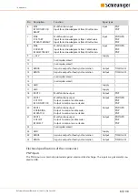
Page 82: ...which are not covered by the internal protection circuitry This can lead to malfunction or even damage to the EcoCut 3300 14 3 1 POSTFEED interface POSTFEED connector RENCA D Sub 25 pin F RENCA 24 V R...

Page 83: ...ation Output TIA EIA 422 14 not implemented 15 not implemented 16 GND Supply 17 GND Supply 18 ROUT0 Multifunction output Output PNP 19 ROUT1 CCSTOP WSCONVEYOR Multifunction output Output to control a...

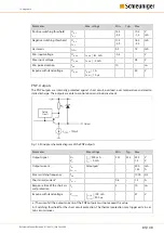
Page 84: ...threshold UIN_T IIN_T 4 8 1 3 8 4 2 4 V mA Hysteresis IIN_T 0 3 1 2 mA Min input voltage UIN_MIN IIN_MAX 1 mA 0 4 V Max input voltage UIN_MAX IIN_MAX 10 3 mA 28 V Min pulse duration tMIN 10 ms Impulse...

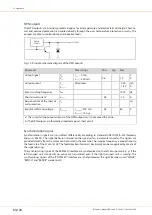
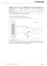
Page 85: ...ture and electro static discharge The outputs are able to control ohmic and inductive loads Output Safety Circuit Fig 13 Principle schematic diagram of the PNP outputs Parameter Max ratings Min Typ Ma...

Page 86: ...100 s 0 3 60 V a The sum of all the output currents of the NPN outputs must not exceed this value b The NPN outputs are thermally protected against short circuit Synchronization signal Synchronizatio...

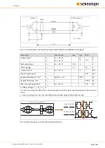
Page 87: ...urrent IOUT RT 100 12 mA Short circuit currentbc IOUT_SC 200 mA Impulse frequency at 1 m s f1m s Speed 1 m s 5950 Hz Impulse frequency max fMAX 12000 Hz Max transmitting distance IMAX RT 100 100 M a O...

Page 88: ...e LENCB RENCB LENCA RENCA LENCA RENCA LENCB RENCB Fig 17 Signal run wire transport direction backward Supply outputs Synchronization signals are transmitted differentially according to standard ANSI T...

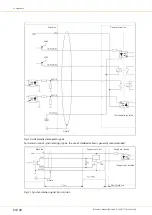
Page 89: ...ons Protection against faults and malfunction The 24 V outputs must not be connected to external power supplies Machine Peripheral device Power supply Controller e g PLC Shielding recommended for long...

Page 90: ...e Galvanically isolated Shield Fig 20 Galvanically decoupled signals For transmission of synchronizing signals the use of shielded cables is generally recommended Signal converter Peripheral device Ma...

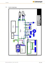
Page 91: ...Display 124 x 64 Frontpanel Folientastatur Kabel endschalter Messer Home Fusspedal RS 232 HS PF Transport Messer Ger testecker A Pre Post Feed Air jet POSTFEED INKJET INTERFACE G Option Option F1 F2...

Page 92: ...49 0 897876 0 Fax 49 0 897876 333 Not applicable Product code 017117 Product description Grease Date of printing 2011 12 01 Date of issue2011 12 01 Classification Not classified See Section 11 for mor...

Page 93: ...ssification See Section 16 for the full text of the H statements declared above 1 Substance classified with a health or environmental hazard 2 Substance with a workplace exposure limit 3 Substance mee...

Page 94: ...tained breathing apparatus SCBA with a full face piece operated in positive pressure mode Clothing for fire fighters including helmets protective boots and gloves conforming to European standard EN 46...

Page 95: ...id environmental contamination SECTION 7 Handling and storage The information in this section contains generic advice and guidance The list of Identified Uses in Section 1 should be consulted for any...

Page 96: ...ols No special ventilation requirements Good general ventilation should be sufficient to control worker exposure to airborne contaminants If this product contains ingredients with exposure limits use...

Page 97: ...not occur SECTION 10 Stability and reactivity 10 1 Reactivity No specific test data related to reactivity available for this product or its ingredients Acute toxicity Residual oils petroleum hydrotrea...

Page 98: ...icant effects or critical hazards Symptoms related to the physical chemical and toxicological characteristics Skin contact Ingestion Inhalation No specific data No specific data No specific data Eye c...

Page 99: ...of environmental protection and waste disposal legislation and any regional local authority requirements Methods of disposal SECTION 13 Disposal considerations The information in this section contains...

Page 100: ...15 Regulatory information 15 1 Safety health and environmental regulations legislation specific for the substance or mixture EU Regulation EC No 1907 2006 REACH Annex XIV List of substances subject to...

Page 101: ...ustomer is responsible for passing on safety datasheets and any amendments contained therein to its own customers employees and other users of the product KL BER LUBRICATION provides no guarantee that...

Page 102: ...14 Appendix 102 108 Reference Manual Edition 4 0 10 2013 EcoCut 3300...

Page 103: ...Personal notes Reference Manual Edition 4 0 10 2013 EcoCut 3300 103 108...

Page 104: ...Personal notes 104 108 Reference Manual Edition 4 0 10 2013 EcoCut 3300...

Page 105: ...Electrical specifications 83 Electromagnetic interference 82 Electrostatic discharge 82 Emergency stop link 16 Entry keys 35 Entry screen 38 Errors 59 F Fault localization 55 Feed speed 40 File not fo...

Page 106: ...ion 40 Rating plate 21 25 Re calibration 61 Registered trademarks 12 Regular inspection 55 RS 232 25 S Safety barrier 16 Safety cover 16 Safety hood 16 Safety interlocks 16 Safety regulations 9 Schleu...

Page 107: ......

Page 108: ......
Reviews: