36
TRACTION LEVERS
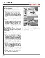
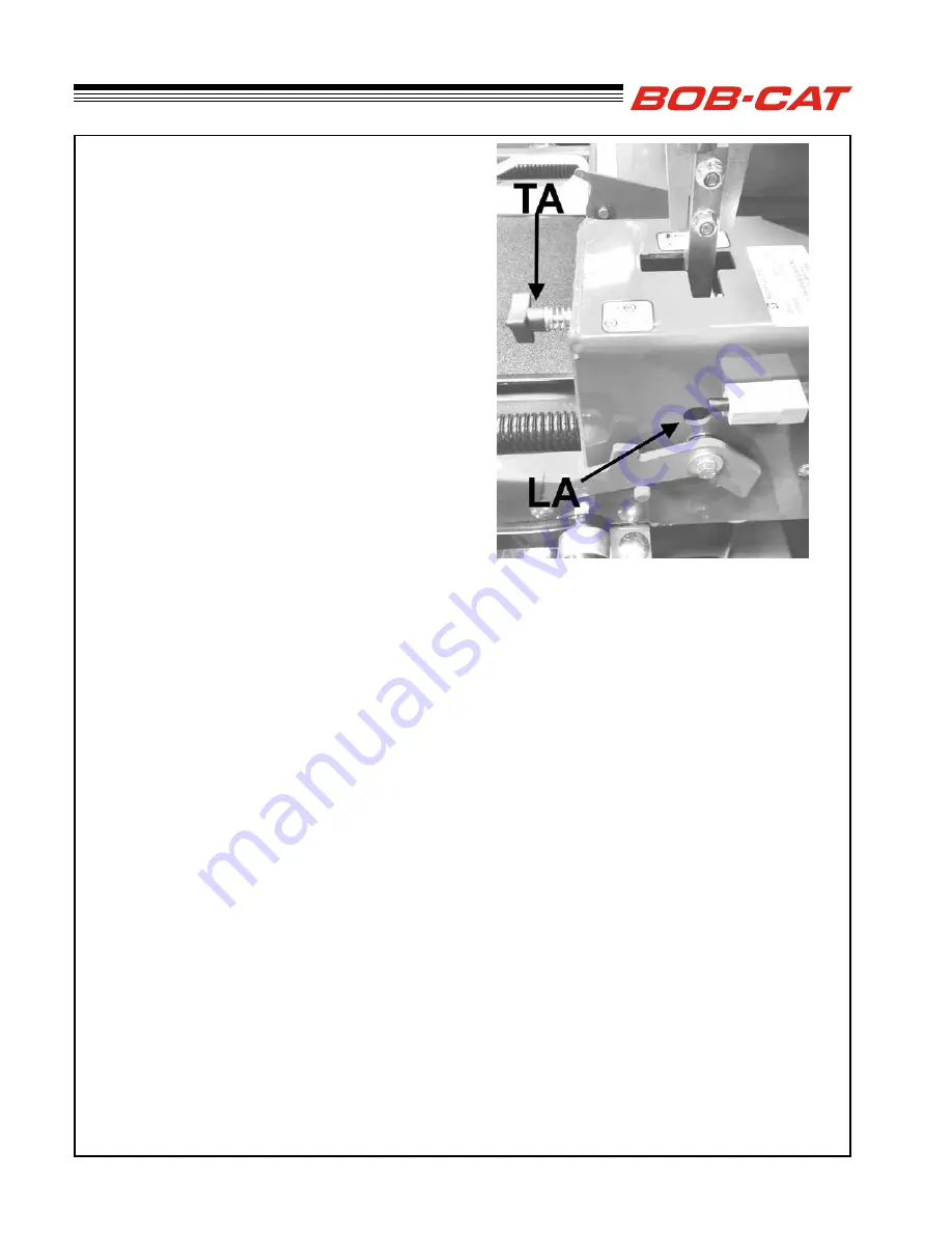
Lateral Adjustment (LA)
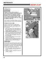
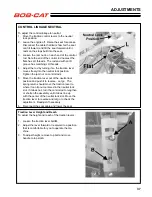
The traction levers are adjustable so they don’t rub
on the guide slots.
1. Make the traction lever lateral adjustment by
putting a 7/16 socket on an extension through
the hole in the side of the frame. Turn in the
adjusting screw until the traction lever just clears
the inside of the guide slot. Repeat for the other
side.
Pivot Tension (LA)
The pivot tension is set by a Belleville washer on the
pivot bolt.
1. Hand tighten the pivot bolt nut 20 ft/lbs against
the Belleville washer until the nut bottoms on the
pivot spacer. Do not over tighten or the spacer
may be crushed. If the spacer is crushed, pivot-
ing the lever may be difficult and it will be hard to
disassemble the traction control.
Tracking Adjustment (TA)
Tracking adjustment is provided so the machine will
go straight when both traction levers are pushed all
the way forward.
To adjust:
1. Turn both tracking adjustment knobs all the way
in.
2. Gently push the tractor control arm forward.
When the traction control stops moving forward
(there should be some slot left). Turn the tracking
adjuster in until it touches the corresponding con-
trol arm so the tracking adjuster limits the stroke
of the traction lever rather than the control stops
on the hydrostat. Repeat for the other side.
3. Find a suitable level, open area. Get on the ma-
chine and start the engine. Run it at half throttle
for better control.
4. Point the machine in a safe direction and drive it
with both traction levers pushed completely for-
ward. If the machine drives straight you are done.
If it drifts off a straight line:
5. Stop the machine, move the traction levers to the
neutral position and set the parking brake. Turn
in the tracking knob on the outside of the drift 1/6
turn
6. Drive the machine again and repeat the adjust-
ment until the machine drives straight.
Note: Regardless of tracking adjustment there will
be a tendency of the machine to drift to the downhill
side of a cross slope.
ADJUSTMENTS
Summary of Contents for 9995010
Page 47: ...45 PARTS SECTION PARTS SECTION ...
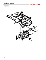
Page 50: ...48 FIGURE 2 BUMPER WRAP 4 3 6 2 7 8 9 10 1 5 5 ...
Page 70: ...68 FIGURE 12 FOLDING ROPS 10 7 5 2 6 13 1 14 1 11 3 1 4 9 8 7 5 3 2 9 4 6 12 15 15 ...
Page 82: ...80 FIGURE 18 DECALS 9 7 17 6 10 13 12 11 1 5 4 6 8 2 3 6 6 16 18 14 20 19 15 ...
Page 84: ...82 7 6 5 4 3 2 1 8 8 4 10 11 12 6 9 13 FIGURE 19 DECALS ...

