33
ADJUSTMENTS
DECK LEVELING
a) Park the machine on a smooth, level surface.
Raise the deck to the transport position.
b) Tires are overinflated for shipping. Set tire pres
-
sures to 12 psi for the rears and 15 psi for the
front pnuematic tires. Note: Tire pressue is not
applicable to flat-free caster tires.
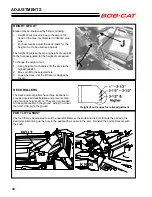
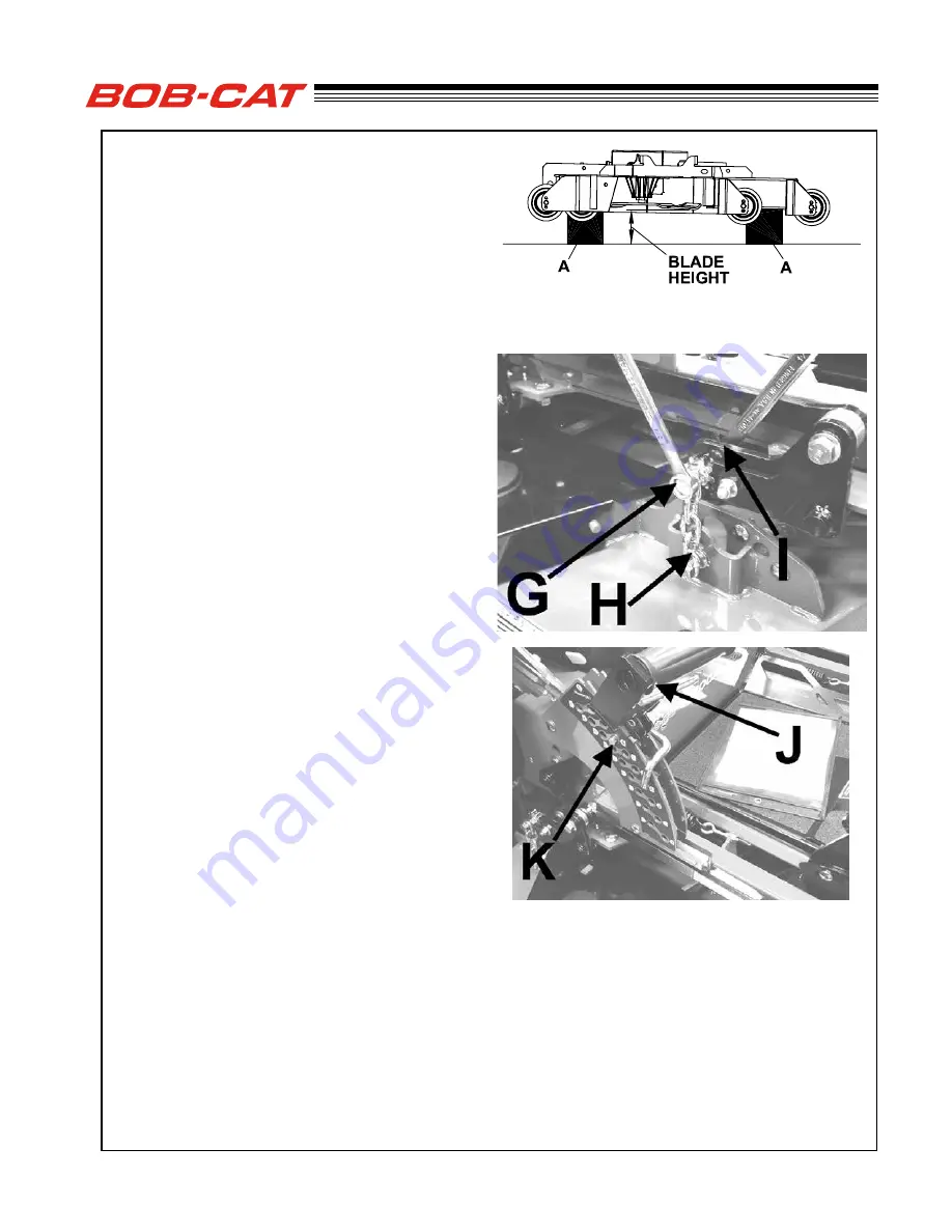
c) Put equal height blocks
A
under the rear corners
of the deck and under the front roller brackets.
The blocks should be 3-1/2” to 4” high to help
minimize effects of the deck counter balance
springs.
NOTE:
The front and rear of the deck are at different
heights, but the bottom of the roller brackets match-
es the bottom of the rear of the deck.
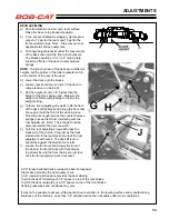
d) Lower the deck onto the blocks
e) Loosen nuts
I
at all four corners of the deck
to
relieve tension on chains
H
.
f) Set the height of cut to 1/4” higher than the
height of the block being used. Measure the
height at a blade cutting edge to confirm the
height setting.
g) Turn the front adjusting screws
G
to lift the front
of the deck off the blocks and snug the front nuts
I
enough to hold the front of the deck in place.
This will put enough load on the counter balance
springs to keep them from interfering with the
rear adjustment. Note: The springs could be
disconnected but that is more work.
h) Turn the rear adjusting screws
G
to take the
slack out of the chains. Stop just as the deck
starts to lift off the rear blocks and lock the rear
adjustment with nuts
I
. The deck lift lever
J
should be against the height of cut pin
K
.
i) Loosen the front nuts
I
and lower the front of
the deck to the front blocks with front adjust-
ing screws
G
until the front chains are just taut.
Lock the front adjstment with front nuts
I
.
A 1/8” forward pitched deck provides the best horsepower.
A level deck provides the best quality of cut.
A 1/8” rearward pitched deck provides the best striping.
To pitch the deck forward put a 1/8” spacer on top of the rear blocks.
To pitch the deck rearward put a 1/8” spacer on top of the front blocks.
Certain grass types and conditions may vary.
It may not be possble to get everything perfect due to variation in the leveling surface and manufacrturing
tolerances of the machine. Less than 1/8” variation will not be noticeable under most condidtions.
Summary of Contents for 9995010
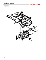
Page 47: ...45 PARTS SECTION PARTS SECTION ...
Page 50: ...48 FIGURE 2 BUMPER WRAP 4 3 6 2 7 8 9 10 1 5 5 ...
Page 70: ...68 FIGURE 12 FOLDING ROPS 10 7 5 2 6 13 1 14 1 11 3 1 4 9 8 7 5 3 2 9 4 6 12 15 15 ...
Page 82: ...80 FIGURE 18 DECALS 9 7 17 6 10 13 12 11 1 5 4 6 8 2 3 6 6 16 18 14 20 19 15 ...
Page 84: ...82 7 6 5 4 3 2 1 8 8 4 10 11 12 6 9 13 FIGURE 19 DECALS ...


