38
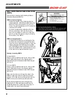
HYDROSTAT NEUTRAL ADJUSTMENT
The hydrostats used on this machine are factory set
in neutral and should never require adjustment. If for
some reason the neutral position on the hydrostat
needs to be reset use the following procedure:
1. Raise the machine. Support it on jack stands.
2. Remove the drive wheels to gain access to the
control linkage on the hydrostat. Raise the seat
to gain access to the control rod assembly. Dis-
connect the control rod assembly. Make sure the
bypass valve is closed. Set the parking brake to
the “OFF” position.
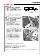
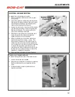
3. Note that the control rotates freely in one direc-
tion (forward) but is spring load in the opposite
direction. This is a unidirectional return-to-neutral
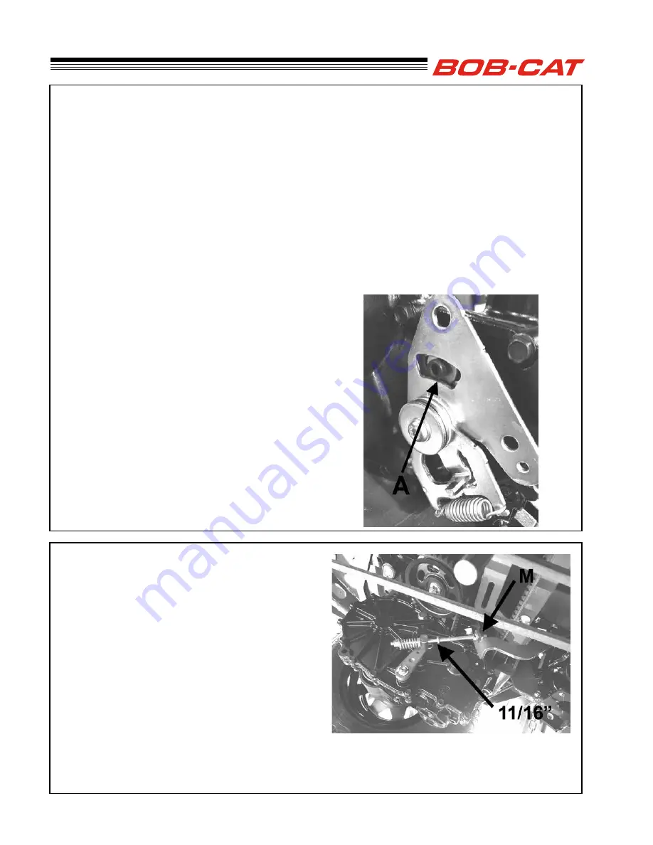
(RTN). Loosen the Neutral Lock hex socket
head cap screw
A
that locks the neutral arm.
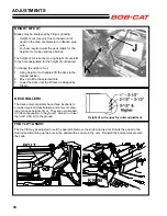
PARKING BRAKE
The parking brake needs to be adjusted so the spring
is compressed 1/4” beyond the pre-compression
when the brake is applied. Four threads of the brake
rod should extend beyond the spring retaining nut on
each end.
1. Loosen the jam
M
nuts locking the brake rod to
the brake link.
2. Apply the brake.
3. Adjust the upper nut by tightening or loosening it
until the gap between the swage on the rod and
the swivel is 11/16". Tighten the other nut on the
brake link to lock the adjustment.
ADJUSTMENTS
4. Start the engine. Stay clear of any moving parts
including the wheel hub.
5. Rotate the entire control assembly, keeping the
reverse return side against the neutral arm to
the point where the wheel hub stops moving.
Tighten the Neutral Lock capscrew, then run the
engine up to full speed. Rotate the control lever
to forward and back against the reverse stop to
check the setting. Readjust if necessary.
6. Stop the engine. Reset the control rod assembly
as outlined above under Control Linkage Neu-
tral.
7. Attach the drive wheels and lower the machine
to remove the jackstands.
Summary of Contents for 9995010
Page 47: ...45 PARTS SECTION PARTS SECTION ...
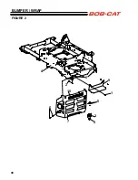
Page 50: ...48 FIGURE 2 BUMPER WRAP 4 3 6 2 7 8 9 10 1 5 5 ...
Page 70: ...68 FIGURE 12 FOLDING ROPS 10 7 5 2 6 13 1 14 1 11 3 1 4 9 8 7 5 3 2 9 4 6 12 15 15 ...
Page 82: ...80 FIGURE 18 DECALS 9 7 17 6 10 13 12 11 1 5 4 6 8 2 3 6 6 16 18 14 20 19 15 ...
Page 84: ...82 7 6 5 4 3 2 1 8 8 4 10 11 12 6 9 13 FIGURE 19 DECALS ...


