10
LAWNAIRE ZTS
ASSEMBLY / CONTROLS
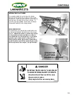
ASSEMBLY / SET UP INSTRUCTIONS
1. READ THE OPERATOR'S MANUAL BEFORE ASSEMBLY.
2. Remove the brackets securing the machine to the pallet. Reinstall the caster axle nuts. Tighten the nuts.
Fill tires at pressure at 15 psi on the rear tires and 25 psi on the front tires.
3. Lower the operator platform.
4. Open the rear panel and connect the ground wire to the battery.
5. Check the oil level in both the engine and the hydraulic tank, top off if necessary.
Use 10w30 oil for the engine.
Use 15w50 or 20w50 motor oil for the hydraulic tank.
6. Fill the fuel tank with fresh clean regular grade gasoline. Open the fuel valve.
7. Start the machine and drive it off the pallet.
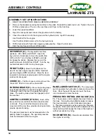
KEYSWITCH (A)
-
The keyswitch has three
positions: OFF, RUN, and START. Insert the
key and turn it clockwise to move the switch from
OFF to RUN. Turn it further to START and hold
to engage the starter. Release the key and the
switch will return to RUN from START. Turn the key
counterclockwise to OFF to stop the engine.
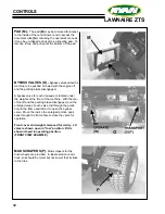
THROTTLE (B)
-
Move the throttle lever for-
ward to increase engine speed until the maximum
governed engine RPM is reached. Move the lever
rearward to decrease engine speed until the engine
reaches its idle speed.
CHOKE (C) -
Pull the choke control out to set the
choke ON. Push it in to set the choke OFF.
PARKING BRAKE (H) -
Move the parking brake
lever forward to latch it in the OFF position. Move
it sideways and to the rear to engage the parking
brake. The parking brake must be engaged to start
the machine.
CONTROL LEVERS (E1 & E2)
- Each of the
two control levers controls the drive wheel located
on its side. They control the forward and reverse
movement of the machine, provide steering and also
provide dynamic braking.
The operator presence must be released when the
parking brake is engaged. The operator presence
must be released to start the engine.
RAISE-LOWER SWITCH
(F)
- The raise-lower
switch operates the hydraulics to raise and lower the
tines. Rock the switch forward to lower the tines,
rock it rearward to raise the tines.
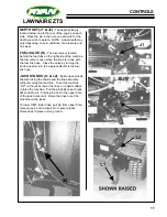
PRESSURE CONTROL AND GAUGE
(G &
I )
- The pressure control adjusts the down force on
the tines. Turning the knob
(G)
clockwise increases
the down pressure, counter clockwise decreases
it. The down pressure may be read on the Pressure
Gauge
(I)
. Down pressure should be adjusted to the
lowest setting which keeps the tines at the depth set
without excessive bouncing.
HOUR METER (M)
- Records accumulated time
the engine is running.

