background image


Chapter 4 

– Integrated Diagnostic PROFIBUS slave 


4. Integrated PROFIBUS diagnostic slave


The WP-3000 master may be equipped with a diagnostic slave 
(DS). Besides the transparent transmission path the WP-3000 
gets therefore its own DP address. 


The diagnostic slave allows you to measure the transmission 
path. The software provides the PROFIBUS master with a 
variable containing internal values and conditions of the 
transmission path. More information can be found in chapter 
6. 


4.1.  Performance limits


Please observe the following performance limits: 


The number of PROFIBUS DP slaves is limited to 

4 (model 3706-4) and 7 (model 3706-7). 


The number of radio receivers is limited 


If you use PROFIBUS Master OP/AG/PG the delays 

can increase. Please optimize your list of transmitted 
variables correspondent to the Siemens recommends 


Radio links are in principle factor 1000 slower and less 

robust compared to a cable link 


Ask yourself: W hat is the effect in the application in case 

of loosing data updating for 1 second? If you expect 
critical effects tell us this in your inquiry 


Summary of Contents for Westcon 3706-1

Page 1: ...less PROFIBUS models 3706 1 3706 4 and 3706 7 Representante e Distribuidor Exclusivo no Brasil WESTCON Instrumentação Industrial Ltda Rua Alvaro Rodrigues 257 CEP 04582 000 Sao Paulo SP Brazil Valid for all WP 3000 Series models 3706 1 3706 4 and 3706 7 01 07 2010 ...

Page 2: ... instructions Warranty Schildknecht AG can accept no liability for indirect damage or direct damage incidental damage consequential damage or compensation for expenses incurred by performance of contract which arise from delivery provision and use of this material Introduction The technical description of wireless data systems from Schildknecht AG consists of one operating instruction for the prod...

Page 3: ...tant things to say about safety Please observe these instructions without fail in order to prevent damage to machinery and injury to persons We show you step by step how to put the wireless data system into operation and how to operate it Any questions Before you do anything else always look in the table of contents You are sure to find what you need there And if you do need us in person just cont...

Page 4: ...Important information 5 1 5 2 Assembly of wireless modem 5 2 5 3 Antenna assembly 5 3 5 4 Electrical connection 5 4 6 Settings 6 1 6 1 General information 6 1 6 2 System stop prevention 6 2 6 3 Basic and PROFIBUS settings 6 3 6 3 1 Step 1 Basic settings at modems 6 4 6 3 2 Step 2 Test wireless modems 6 8 6 3 3 Step 3 PROFIBUS settings 6 12 6 3 4 Step 4 Optimization coexistence setting 6 18 7 Worki...

Page 5: ...mproving the EMC safety 8 1 8 1 1 Introduction 8 1 8 1 2 Basic rules 8 1 8 2 Guidelines for optimized installation of antennas 8 5 8 3 Advice for trouble shooting 8 10 9 Release list of foreign devices 9 1 10 Technical data 10 1 ...

Page 6: ...portant information Indicates work operations which need to be carried out This symbol is followed by a description about how the status of the system changes after an operation has been carried out 1 2 Trade marks Trade names and product names mentioned in this document are trade marks or registered trade marks of the individual title holders STEP 5 STEP 7 S5 S7 S7 200 S7 300 S7 400 are trade mar...

Page 7: ...ree operation the according safety instructions have to be observed Safety instructions which apply to all system families are described in the operating instruction Wireless data systems WP 3000 This instruction is an integral part of the total documentation Safety instructions which apply for an individual wireless data system only or which are related to assembly and commissioning are described...

Page 8: ...dividuals for the purpose of safety instructions are those individuals who are authorized to commission ground and label devices systems and electric circuits according to the safety standards The operating personnel have to be instructed and trained accordingly Individuals who operate controllers must have profound programming knowledge about the particular controller and programming language ...

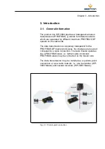
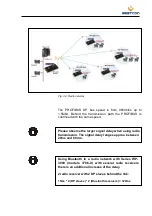
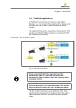
Page 9: ...ata transmission is completely transparent for the PROFIBUS DP master and slaves No changes are required compared to a cable connection The radio master operates like a PROFIBUS slave i e further cable connected PROFIBUS slaves may be connected on the master side The data transmission may be installed as a point to point connection or as a radio network i e one transmitter WP 3000 Master and sever...

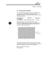
Page 10: ...ease observe the larger signal delay when using radio transmission The signal delay ranges approx between 20ms and 80 ms Using Bluetooth in a radio network with Series WP 3000 models 3706 X with several radio receivers there is an additional increase of the delay 2 radio receiver with 2 DP slaves behind the link 15ms 4 DP slaves 2 Bluetooth receivers 120ms ...

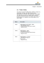
Page 11: ...products are identical in terms of structure and function i e the description for installation and settings applies to all device types Model Description 3706 7 PROFIBUS DP and ProfiSafe 1 5Mbit 7 PROFIBUS DP slaves or 7 radios WP 3000 model 3706 7 slaves diagnostic slave 3706 4 PROFIBUS DP 1 5Mbit 4 PROFIBUS DP slaves or 4 radios WP 3000 model 3706 4 slaves diagnostic slave 3706 1 PROFIBUS DP 187...

Page 12: ...3 with input modules Funkmedium radio transmission medium Fig 3 2 WP 3000 and Profisafe Check unconditionally if the signal delay of the transmission path or a possible interrupt of the transmission path actuation of the SIL monitor affect any safety criteria Practical experience has indicated that the SIL monitor time should be increased to a min of 500ms to 800ms The SIL monitor time has to be s...

Page 13: ...vice type Delay typical 2 4GHz Bluetooth 3706 7 3706 4 and 3706 1 25 ms These time delays are caused by the device internal PROFIBUS wireless protocol handling From experience an increase of the PROFIBUS speed beyond 500kbit s does not yield to further improvements This chart shows the coherence of amount of data number of DP slaves behind the radio link and amount of receivers to the data exchang...

Page 14: ...re information can be found in chapter 6 4 1 Performance limits Please observe the following performance limits The number of PROFIBUS DP slaves is limited to 4 model 3706 4 and 7 model 3706 7 The number of radio receivers is limited If you use PROFIBUS Master OP AG PG the delays can increase Please optimize your list of transmitted variables correspondent to the Siemens recommends Radio links are...

Page 15: ...a transmission Please observe during installation that WP 3000 master and slave are designed differentially The devices are labeled accordingly The WP 3000 master acts as a PROFIBUS slave for the controller but has not to be integrated into the PROFIBUS network The transmission path is transparent The WP 3000 slave s takes control of the PROFIBUS devices on the other side of the transmission path ...

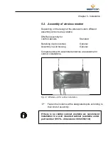
Page 16: ...horizontal Optional Assembly in wall housing Optional Complete units with assembled antennas are available for outdoor installations Fig 4 1 Wireless unit for outdoor installation Fasten the modems at the designated spots according to their kind of assembly If there is no control cabinet available we recommend installation in a wall mounted cabinet available under part number 10578 dimensions 380x...

Page 17: ...a assembly Connect the antenna cable with the antenna connection of the modem Fasten the antenna at the according locations Please pay attention to the guidelines about optimal antenna assembly as described in chapter 8 Tips and Tricks ...

Page 18: ...has to be connected with control cabinet ground If the PE is not connected the noise filter cannot filter interferences on 24 V DC power supply line These may cause malfunctions errors or the destruction of the device CAUTION The nominal operating voltage of 24 V DC falls into the category SELV safety extra low voltage and is thereby no subject to the EC low voltage directive Usage of other power ...

Page 19: ... the supply voltage After connecting the power supply the display shows for approx 1 sec the message DE aaaa V x y Init Medium aaaa Type e g DE3703 x y Software revision For compatibility reasons always devices with the same hardware and software revision should be used together The hardware revision can be found on the type plate at the rear side of the device Please contact Schildknecht AG for d...

Page 20: ...lished if the factory settings have not been changed and a cable connection to the DP devices has been established the modems start to initiate a data transmission as soon as the power supply is connected If data is transmitted the displays show the following messages Modem 1 Modem 2 P 01 S 02 F P 02 S 01 F The modems are now in their initial state and you may start with the settings or operating ...

Page 21: ...ted by the manufacturer It is recommended to verify the allocation Access to the identification number Proceed with the following steps to access the identification number Press the button Arrow right Connect the power supply The display shows the identification numbers which are explained subsequently Assembly and commissioning instructions DATAEAGLE 3000 5 8 ...

Page 22: ...t of the ARI number In a multi master radio transmission system two radio masters ARI and DECT number have to be identical in both masters Read off the ARI and DECT number at one master and write it down Call the identification number at the slaves and if necessary also at the second master Enter the ARI number at all slaves and if necessary also at the second master Don t forget the DECT number a...

Page 23: ...dems Only modules with identical MAC numbers are able to communicate with each other Read off the MAC number at the DATAEAGLE master and write it down Call the identification number at the slaves Enter the MAC number at all slaves Use the buttons arrow right and arrow left to place the cursor below the correct position Select with the buttons arrow up und arrow down the correct number Acknowledge ...

Page 24: ...parent for the PROFIBUS master and slave Settings which have to be executed during commissioning are described in chapter 5 4 Further settings and operation of the wireless transmission series WP 3000 are described extensively and with description of backgrounds and correlations in the operating instruction Wireless data systems DATAEAGLE DE2000 and 3000 ...

Page 25: ...ave a process image of the inputs of a PROFIBUS slave before they are reset the following method should be applied Copy the inputs of a slave cyclically in an array When the slave fails the OB 86 will be started Set a flag in this OB which prevents further cyclical copies Reset the flag in the OB when the slave is back at the bus Eventually either OB 85 or OB 122 may be started before OB 86 is sta...

Page 26: ...tings The flow chart below shows on a glance which settings should be executed in which sequence Step 1 Basic settings Step 2 Test of the radio transmission path Step 3 PROFIBUS settings on DATAEAGLE Master Step 4 Optimization Coexistence settings ...

Page 27: ...isplay shows Password 000 The password is factory set to 000 You may change the password at a later time Related information can be found in the operating instruction Wireless data systems DATAEAGLE DE2000 and 3000 chapter 7 4 7 Press the button Enter Press the button arrow right until the display shows Change device address Press the button Enter Assembly and commissioning instructions DATAEAGLE ...

Page 28: ...nk are not available it will case longer reaction times und slow down the communication The field XXX is for parameterization of this characteristic XXX ON means that the radio slave will always be in the radio network XXX OFF radios lave is in the net but actually not reachable maintenance XXX DYN DATAEAGLE tries to reach the slave all 20 seconds If you like to build up a radio network do it in t...

Page 29: ... the radio slave recommended ON Confirm with Enter Stations address is the radio address for the master select a unique user defined one If there are additional radio slaves go to list position select 02 and change the corresponding partner addres Do it in the same way for all radio slaves Please note Select only addresses from real existing radio slaves If you like to clear a list position write ...

Page 30: ...0 Slaves in the radio net needs the address of the corresponding WP 3000 master werden Partneradress aa Stationsadress bb DE 3xxx A Slave Partner address is from the WP 3000 master Stations address is user defined but unique in the net value from 1 to 99 Now you have finished the basic settings ...

Page 31: ... configured for a first transmission test which consists of two steps Step 1 Check if a data transmission takes place Step 2 Check the quality of the data transmission Assure that no modem is connected to a controller Assure that all modems are connected to a power supply ...

Page 32: ...t the master modem Proceed with the steps below Press the button arrow right The display shows Password 000 Press the button Enter Press the button arrow right until the display shows Medium functions Press the button Enter The display shows Test Radio channel Press the button Enter Assembly and commissioning instructions DATAEAGLE 3000 6 9 ...

Page 33: ...The measured transmission quality should be in a range of 50 to 100 90 is a typical value for a good transmission Possibilities on how to improve the transmission quality can be found in the operating instruction Wireless data systems DATAEAGLE DE2000 and 3000 If more than one slave modem is operated in the wireless system the steps below should be executed Otherwise proceed with chapter 6 3 3 Pre...

Page 34: ...w the first digit of the remote address Enter the station address of the second slave modem as remote address see chapter 6 3 1 Master modem and slave modem 2 try immediately to establish a data transmission Repeat steps 2a and 2b for all slave modems You have now completed step 2 and checked all transmission paths ...

Page 35: ...ace Driver Press the button Enter The display shows Masterside GC Time 000x0 5s The radio master transmits cyclically and after a change of the operating condition of the DP master a Global Control telegram to all connected slaves This happens every 5 seconds at standard setting 000 This time can be changed in steps of 0 5 seconds to assure a maximum compatibility with DP slaves from different sup...

Page 36: ...er within the PROFIBUS network If you want to use the diagnostic function you have to enter all addresses now Enter the desired diagnostic slave address by using the buttons arrow up and arrow down to select the correct number Use the buttons arrow right and arrow left to place the cursor below the correct digit Press the button arrow right until the cursor is placed below the first digit of the d...

Page 37: ...d D Field A Position in the table Meaning of the fields The WP 3000 administrates all DP slaves which are addressed by wireless data in a table One DP slave address can be entered in each table position see field B Max 32 table positions exist The allocation of the DP slave addresses to a table position is freely selectable Gaps are allowed A different amount of DP slaves may be addressed in the d...

Page 38: ...s arrow up and arrow down to select a value 01 04 or 01 07 Place the cursor into field B Enter the desired DP slave address by using the buttons arrow up and arrow down to select the correct number Use the buttons arrow right and arrow left to place the cursor below the correct digit Unused table positions are represented by the value 127 i e SA 127 Press the button Enter if you would like to ente...

Page 39: ...short radio interferences If a DE slave cannot be accessed due to an interference a bus error is indicated to the PROFIBUS master only after the filter time has been elapsed Only then are the outputs of the slaves switched into safe condition Max setting range 003 0 1s 300ms to 255 0 1s 25 5s The filter time should be increased under the following conditions Slave has many I O data Many slaves sho...

Page 40: ...y as long as the selected SIL monitor time Please verify therefore if your application meets the required safety criteria with the selected filter time Select Filter time Exit menu Press the button arrow right until the cursor is placed below the first digit of the filter time Select a filter time by using the buttons arrow up and arrow down Use the buttons arrow right and arrow left to place the ...

Page 41: ...ogy Blacklisting of WLAN channels This picture left hand bottom side shows the mode of operation of this coexistence feature of WP 3000 Channels 1 6 11 are blocked The red dots are the used frequencies by Bluetooth the green area the unused bandwidth for WLAN usage On channel 11 is a working WLAN Access Point Go in the radio master menu Press button arrow right In the display you see the message P...

Page 42: ...t be used by WP3000 radio s Bluetooth Press arrow right until cursor jumps to the first digit of the WLAN channel field Set the desired channels by pressing buttons arrow up and arrow down until the correct digit is in the display Use arrow right and arrow left to set the cursor on the right position Unused entries has to set to 00 Press Enter and 2 x ESC to close the input and go to the next step...

Page 43: ...git of the transmitting power field Now you can set the maximum value by pressing arrow up or arrow down Using arrow right or arrow left to set the cursor on the accurate position Press Enter and 2 x ESC to finish the input Field Hide x can switch the invisibility for other Bluetooth devices from J invisible for other Bluetooth devices Default to N visible For diagnostic reasons it could be necess...

Page 44: ...king with the diagnostic slave 7 1 General information The diagnostic slave is a powerful tool for monitoring the transmission path The diagnostic slave enables the user to perform extensive diagnostics and to visualize long term characteristics on the transmission path With its own DP slave address see chapter 6 6 3 PROFIBUS settings an PLC can access and process diagnostic data The PLC can be th...

Page 45: ...tion This way you can reduce PROFIBUS bus errors at the PLC with a high filter time By monitoring the initializing counter you can detect even the smallest radio interruptions before they are recognized by the system as a PROFIBUS error For optimization use the data from Block 5 Application 3 Problems during commissioning Sometimes it occurs that the transmission path does not operate during commi...

Page 46: ...of operation The illustration shows the mode of operation in principle Step 1 The PLC addresses the diagnostic slave and selects a data block Step 2 The diagnostic slave provides the selected data block Step 3 The PLC reads the data block ...

Page 47: ...e Hardware configuration Select Install GSD files in the menu Extras After successful installation you will find the DE3002 diagnostic slave in the hardware catalogue under PROFIBUS DP Weitere Feldgeräte Allgemein DE3002 Diagnose Integrate the diagnostic slave into the PROFIBUS network and assign the PROFIBUS address which you have set for the diagnostic slave at the radio master see chapter 6 3 3...

Page 48: ... 100 RET_VAL MW0 RECORD P DB100 DBX 0 0 BYTE 32 Example Send data from DB101 starting from DBB0 to the diagnostic slave The memory address of the diagnostic slave see hardware configuration is 256 100hex The error code will be saved in MW2 CALL DPWR_DAT LADDR w 16 100 RECORD P DB101 DBX 0 0 BYTE 32 RET_VAL MW2 Controlling the diagnostic slave The byte 0 of the transmitting data DB101 DBB0 in the a...

Page 49: ...page 0 to 7 0 to 7 Byte 1 Controller Bit 0 1 resets the counters Additional parameters depending display page 0 without function 1 reset counters 0 255 Byte 2 to 30 Parameter depending on the display page 0 255 Byte 31 Reserved 0 Receiving data from diagnostic slave Diagnostic data Chapter 7 Diagnostic slave ...

Page 50: ...all interrupted connections from the transmitter side radio master reports bus error Byte 8 9 Sum of all slave responding telegrams Byte 10 13 Radio device type ASCII coded e g 3002 Byte 14 17 Radio Software version ASCII coded e g 9 75 Byte 18 21 Software PROFIBUS inter face ASCII coded e g V 42 Byte 22 Radio channel Set radio channel depending on DE type Byte 23 HF Retries Set HF Retries Byte 24...

Page 51: ...ernal state machine allows the diagnosis of the internal PROFIBUS interface Under normal conditions it shows 5 If no communication with the slaves can be established e g because the connected slaves are not compatible you may run a remote diagnosis Block 3 Response time of the slaves Data exchange time Position Meaning Status Value Control Value Byte 0 Response time slave 1 Time frame 10ms Display...

Page 52: ... Value Control Value Byte 0 Number of restarts slave 1 transmission side 0 to 255 Display page here 5 Byte 1 Number of restarts slave 2 transmission side 0 to 255 0 no function 1 reset counter Byte 2 Number of restarts slave 3 transmission side 0 to 255 Byte 31 5 Feedback from display side here 5 Block 6 Number of restarts from DP side Position Meaning Status Value Control Value Byte 0 bis 7 Numbe...

Page 53: ...ave2 0 to 99 127 slave not present 0 no function 1 automatic mode 255 radioslave 2 off Byte 30 Radio address of slave30 0 to 99 127 slave not present 0 no function 1 automatic mode 255 radioslave 30 off Byte 31 8 Feedback from display side here 8 Radio 3706 n Master tries to connect cyclic all radios laves which he knows thru the partner address list see page 6 10 In some applications parts of the...

Page 54: ...ve 1 0 to 255 seconds 0 no function 1 reset counter Byte 2 Maximum timeout of slave 2 0 to 255 seconds 0 no function 1 save highest timeout value Byte 30 Maximum timeout of slave 30 0 to 255 seconds Byte 31 10 Feedback from display side here 10 Block 255 Reset all counters for all pages Position Meaning Status Value Control Value Byte 0 Dummy Not defined Display page here 255 Byte 1 Dummy Not defi...

Page 55: ...e immunity will become partly inefficient The interference resistance of the complete system depends highly on the correct installation place of installation and wiring Before installation always check which installation instructions are required by the supplier of the controller for a safe operation These instructions should be consistent with the recommendations given here 8 1 2 Basic rules Grou...

Page 56: ...t least 20 cm away from the power cables if possible in separate cable ducts Connect all unused leads of a cable always on both sides to PE Use metallic or metallized plug housing The shielding of the cable should always be connected to the plug housing Always mount all electronic devices on a galvanized mounting plate in the control cabinet This mounting plate functions as EMC earth neutral point...

Page 57: ...installed in a closed metallic housing Run the protective earth conductors of the individual system components star shaped towards the potential equalization rail Thereby you avoid that interferences are injected by PE loops which act as antennas Unfavorable earth protection connections and loops may bridge EMC measurements and will make them inefficiently Pay unconditional attention to a separati...

Page 58: ...ng points within the building Because the radio modem is only supplied with 24V DC grounding is not necessarily requested Only HF earth is required If a circular current across the screen is measured measure with a clamp on ammeter a DC isolation should be realized by using a X capacitor 100nF 230V The capacitor acts with low impedance against high frequent interferences but avoids circular curren...

Page 59: ...ry to connect antennas to the radios with the shortest possible antenna cable Do everything what is necessary to get a line of side situation between the antennas Try to mount the antenna on a place which is free and high The distance between two antennas which are connected to the same modem should be 10 100 cm for DE 300x 310x 10 100 cm It is a good practice to have a large as possible distance ...

Page 60: ...Chapter 8 Tips and Tricks Install antennas at both modems on the same level Pay attention to the level ...

Page 61: ...ion Distance and free radiation All antennas should have the same orientation e g vertical Not this way Keep sufficient distance to metal parts and walls Keep maximum distance to motors and frequency converters Provide free radiation Max ...

Page 62: ...s Line of sight Out of the control cabinet The best data transmission quality will be achieved when the antennas are installed in a line of sight at an elevated and free location Install antennas outside of the control cabinet ...

Page 63: ...partner address Check the distance towards the partner station Select first a distance of a few meters and increase the distance step by step up to the intended distance Check the antenna connection Check if all antennas are connected correctly Pay attention that coax antenna cable is not flexed Check next if all antennas are installed according to the guidelines described in chapter 8 2 Check if ...

Page 64: ... Here only cold starts of the PLC can help For Simatic S7 there are no incompatibilities known If you connect Simatic HMI like OP or TP keep in mind that there is a big difference in amount of PROFIBUS telegrams which are generated and transferred via the radio link where your data are located in the PLC We recommend to place all transferred data on a common block which could be transferred in one...

Page 65: ...WP 3000 master Bluetooth 2 4GHz 1 100mW models 3706 7 3706 4 and 3706 1 Slave side WP 3000 Slave 7 DP adresses 1 Diagnostic slave models 3706 7 4 DP adresses 1 Diagnostic slave models 3706 4 3 DP adresses 1 Diagnostic slave Point to point radiolink models 3706 1 Interface RS485 PROFIBUS norm PROFIBUS speed up to 1 5Mbit s automatic mirroring from master side For connection of All norm slaves all P...

Reviews: